Loading subject page…


18,855 views
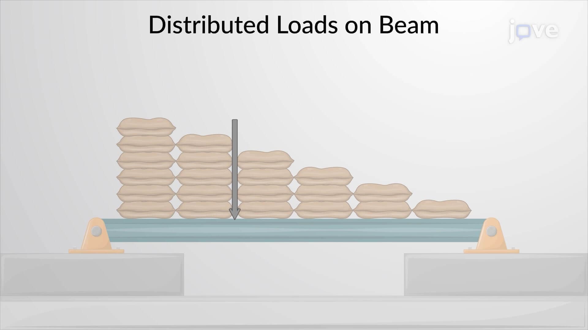

Video Summary: What Is Resultant General Distributed Loading
Ever wonder how engineers calculate the total force when weight spreads across an entire surface, like snow on a rooftop or wind pressure on a skyscraper? Resultant general distributed loading transforms complex distributed forces into a single equivalent force vector. Consider the uniform pressure distribution across the Golden Gate Bridge deck during heavy traffic-engineers must determine both the total force magnitude and its precise location to ensure structural integrity. This concept reveals how distributed loads create resultant forces whose lines of action pass through the centroid of the loading diagram's volume. Watch the full video on JoVE Coach to master this concept with expert-led visuals and step-by-step explanations.
Resultant general distributed loading represents one of the most crucial concepts in structural and mechanical engineering analysis. Unlike concentrated forces that act at specific points, distributed loads spread across surfaces or lines, creating complex force patterns that require sophisticated analysis techniques. The resultant force concept allows engineers to replace these complex distributions with a single equivalent force that produces the same overall effect on a structure.
The magnitude of a resultant force from distributed loading equals the total volume under the loading diagram. For a uniformly distributed load of intensity w across length L, the resultant magnitude becomes F = w × L. However, for non-uniform distributions, integration becomes essential: F = ∫w(x)dx over the loaded region. This mathematical relationship proves invaluable when analyzing complex loading scenarios encountered in AP Physics C mechanics or college-level statics courses.
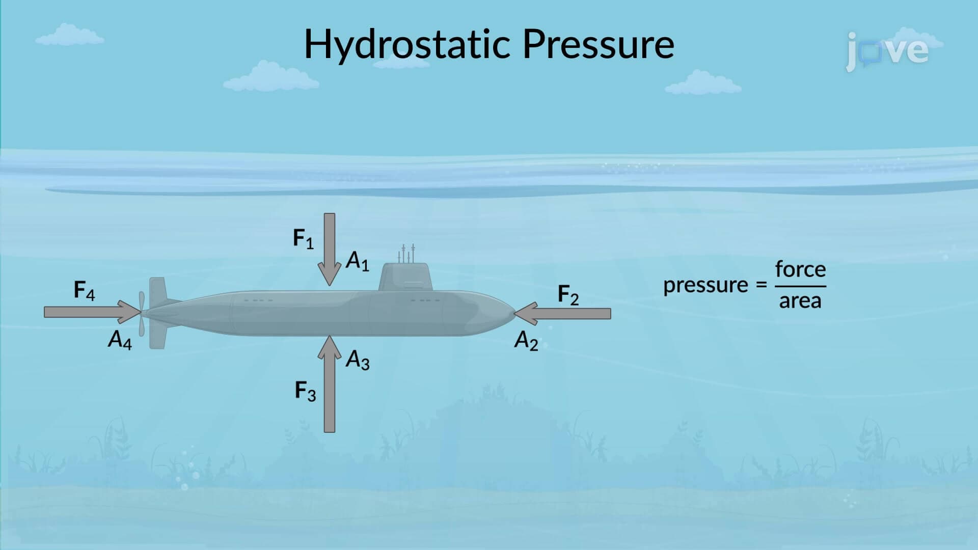
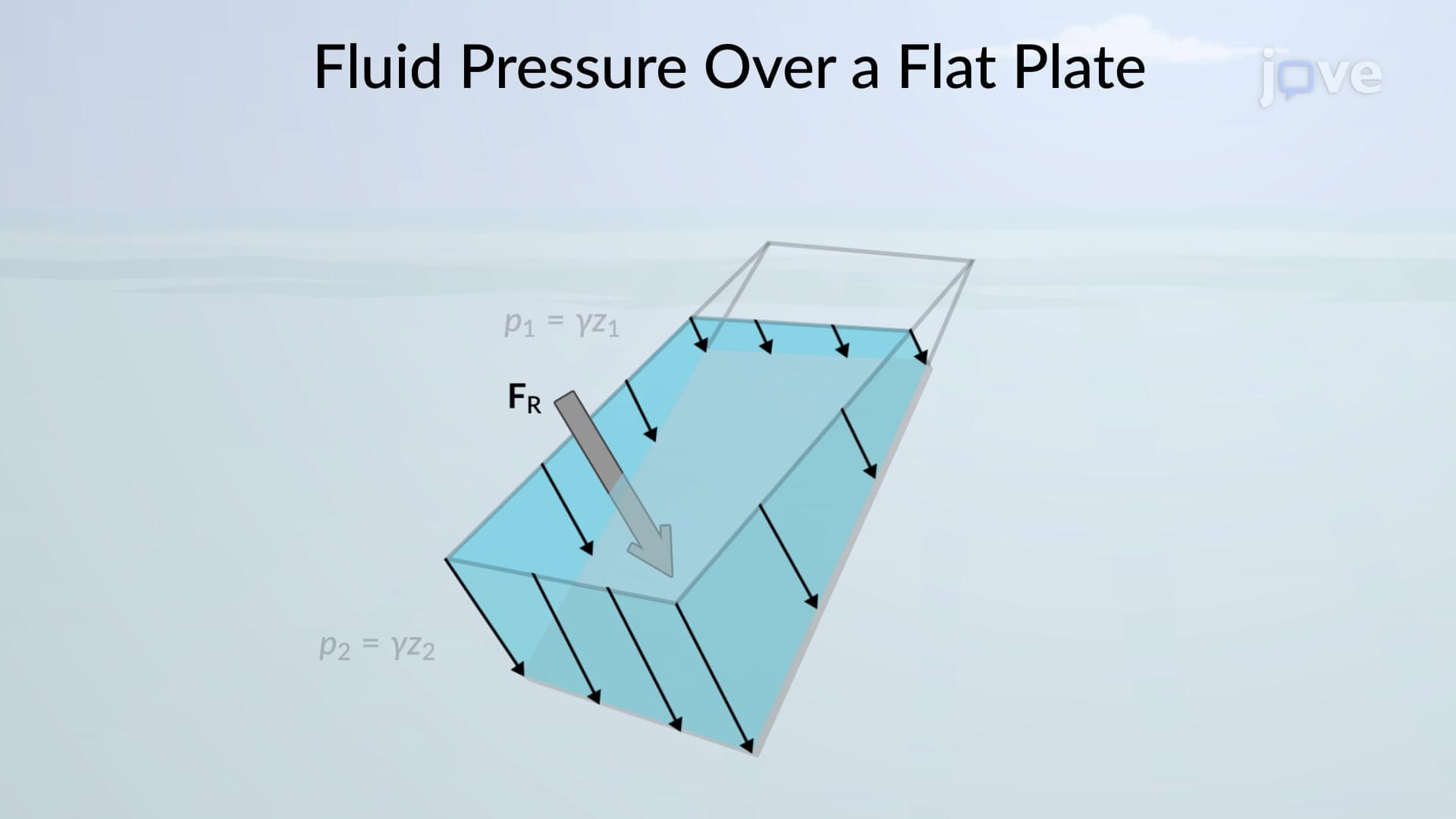
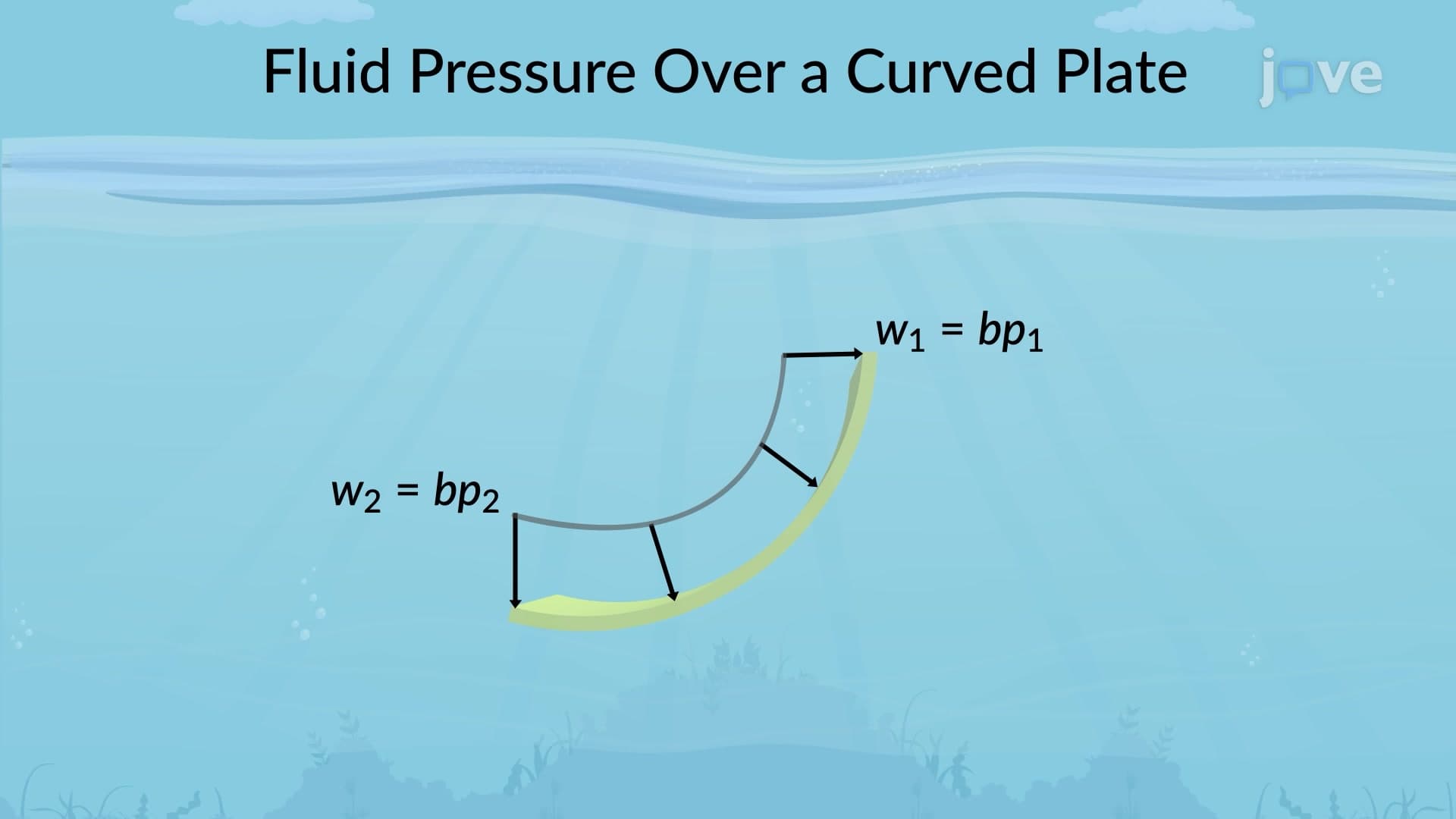
Consider the distributed pressure on a dam face due to hydrostatic water pressure. The pressure increases linearly with depth, creating a triangular loading diagram. The resultant force equals one-half the base times height of this triangle, while its location sits at the centroid-two-thirds of the way down from the water surface.
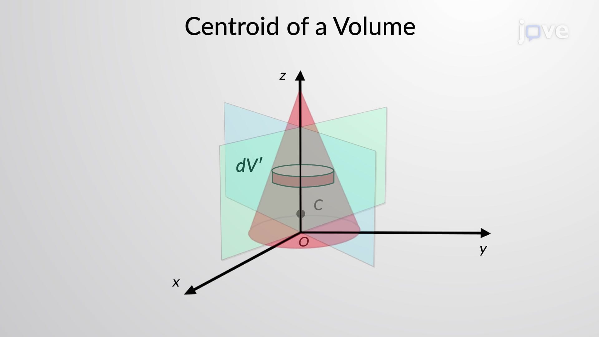
The line of action of the resultant force passes through the centroid of the volume under the distributed loading diagram. This principle stems from moment equilibrium: the moment created by the resultant force about any point must equal the sum of moments from all differential forces. For symmetric loading patterns, the centroid location often follows geometric rules, but irregular distributions require calculus-based centroid calculations using x̄ = ∫x·w(x)dx / ∫w(x)dx.
Distributed loading analysis appears throughout American infrastructure projects. Highway bridge designers must account for vehicle loading distributed across bridge decks, while skyscraper engineers analyze wind pressure distributions on building facades. The Federal Highway Administration requires distributed loading considerations in bridge design specifications, making this concept essential for Professional Engineer (PE) exam preparation.
Aircraft wing design exemplifies complex distributed loading, where lift forces vary along the wingspan according to aerodynamic principles. Boeing engineers use distributed loading analysis to determine wing structural requirements and optimize weight distribution for aircraft like the 737 series manufactured in the United States.
Related Micro-courses