Loading video…


 8 Concepts
 1.9K views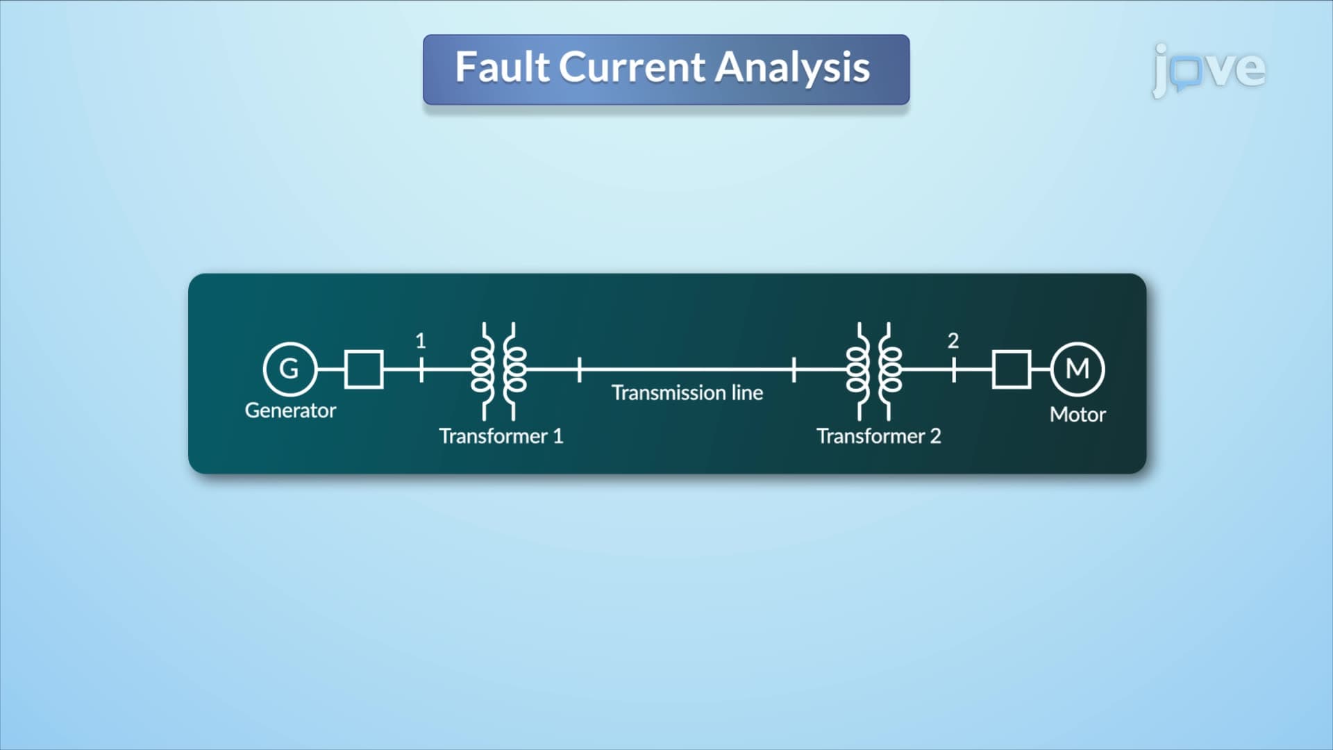

Video Summary: Power System Three Phase Short Circuits Explained
Ever wondered why your entire neighborhood loses power when lightning strikes a single power line? The bus impedance matrix serves as the electrical "GPS" that maps how faults spread through interconnected power systems. When analyzing Power System Three Phase Short Circuits Explained, engineers use this mathematical tool to predict fault currents at every point in networks like the Texas power grid. Watch the full video on JoVE Coach to master this concept with expert-led visuals and step-by-step explanations.
Three-phase short circuit analysis forms the backbone of power system protection design. When a fault occurs in electrical networks-like those serving major US cities such as New York or Los Angeles-engineers must quickly determine fault currents to coordinate protective devices. The bus impedance matrix becomes essential here, providing a systematic approach to calculate these currents across interconnected systems.
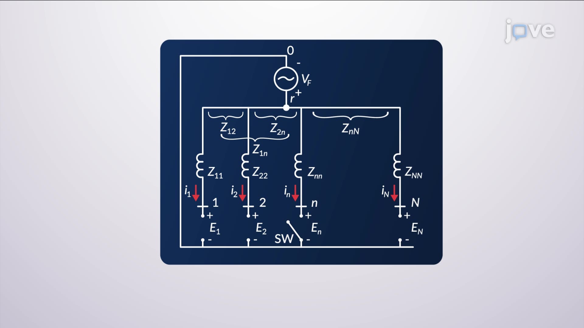
The bus impedance matrix definition centers on representing the impedance relationships between all buses (connection points) in a power system. Each element Z(ij) in this matrix represents the voltage that appears at bus i due to a unit current injection at bus j. This mathematical framework enables engineers to solve complex fault scenarios that would otherwise require solving dozens of simultaneous equations.
For students preparing for AP Physics or college-level electrical engineering courses, understanding what is bus impedance matrix in detail involves recognizing it as a square matrix where diagonal elements represent self-impedances, while off-diagonal elements show mutual impedances between different buses.
The transcript highlights crucial modeling assumptions. Transformers reduce to their leakage reactances-typically 5-15% of their ratings. Transmission lines become series reactances based on their physical construction. Most importantly, synchronous machines (generators and large motors) transform into constant voltage sources behind their subtransient reactances, which represent the machine's immediate response during the first few cycles of a fault.
These simplifications, while excluding factors like resistance and saturation, provide sufficiently accurate results for protective system design. Major utilities like Pacific Gas & Electric use these methods to coordinate circuit breakers and relays across their networks.
The superposition principle splits fault analysis into two parts: the pre-fault system operating normally, and a second network representing the fault disturbance. By combining these using the bus impedance matrix overview, engineers determine total fault currents. This approach proves particularly valuable when analyzing faults on interconnected systems like the Eastern Interconnection, which spans from Canada to Florida.
Students encountering this material in university power systems courses should focus on how the bus impedance matrix streamlines calculations that protect equipment worth millions of dollars and ensure grid stability for millions of customers.
Related Micro-courses