Loading subject page…


1,932 views


Video Summary: Sequence Networks of Rotating Machines Explained
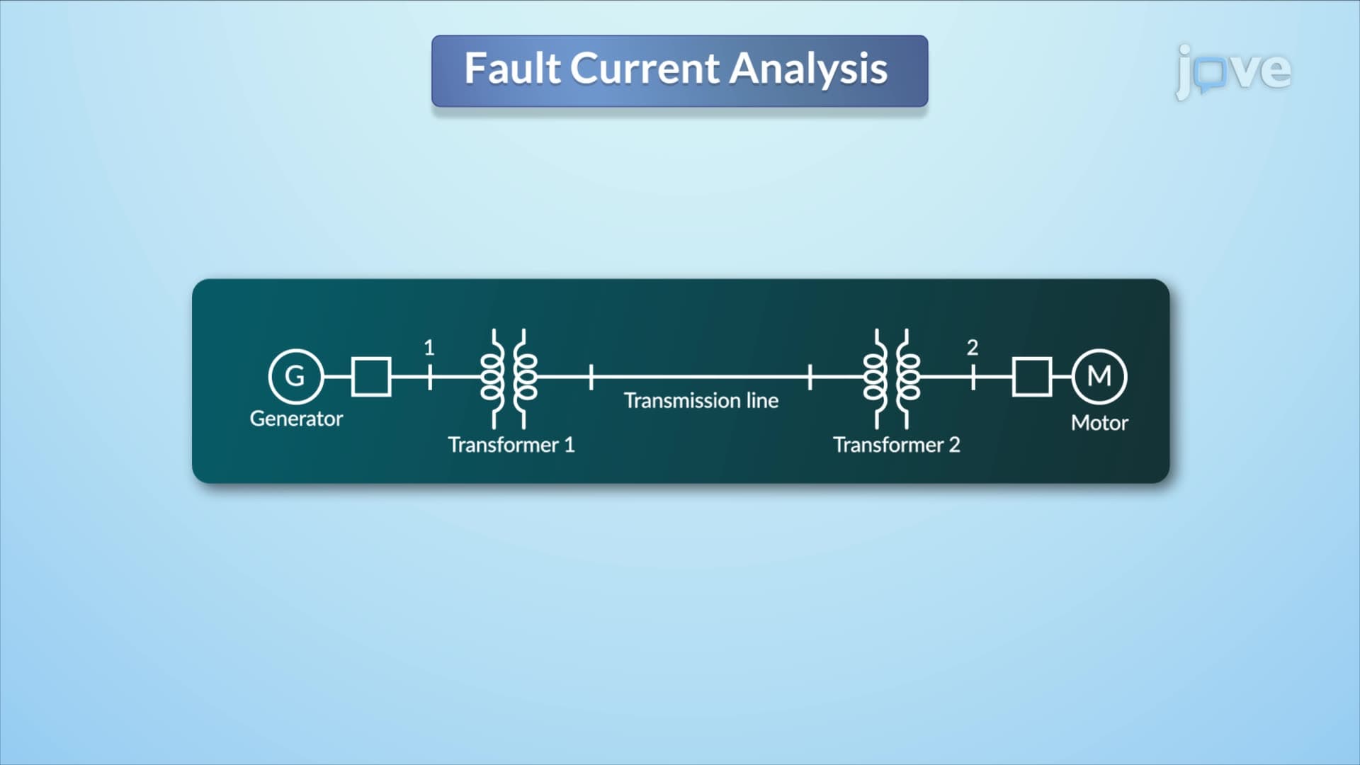
Ever wonder how electrical engineers predict power failures before they happen? Per unit sequence models transform complex three-phase electrical systems into manageable single-phase equivalents, making fault analysis possible. Consider how engineers at Pacific Gas & Electric analyze generator behavior during grid disturbances using these mathematical tools. Sequence Networks of Rotating Machines Explained breaks down how positive, negative, and zero-sequence components model real-world synchronous generators and motors. Watch the full video on JoVE Coach to master this concept with expert-led visuals and step-by-step explanations.
Sequence networks represent one of the most powerful analytical tools in electrical power engineering, transforming complex three-phase systems into three separate single-phase networks. This mathematical approach, developed in the 1920s by Charles Fortescue, allows engineers to analyze both balanced and unbalanced conditions in power systems with remarkable precision.
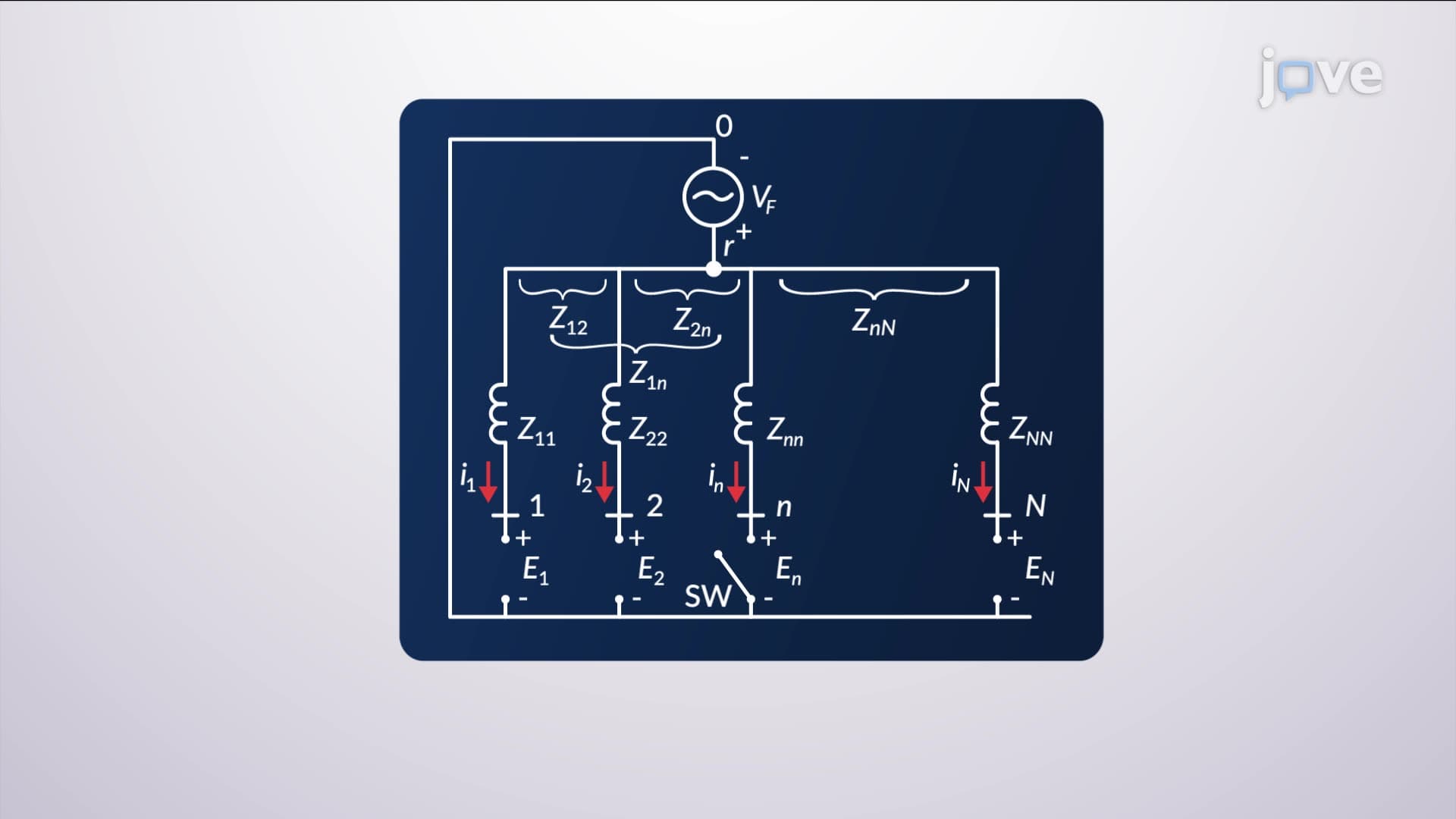
Per unit sequence models normalize impedance values to a common base, creating dimensionless quantities that simplify calculations across different voltage and power levels. In a typical synchronous generator, the positive-sequence network contains the internal voltage source and represents normal operating conditions. The negative-sequence network has no internal voltage source but includes impedance that opposes rotor rotation. The zero-sequence network accounts for ground fault currents and typically has the lowest impedance value.
Engineers classify sequence impedances into three distinct categories based on time constants. Synchronous impedance applies to steady-state conditions and appears in power flow studies for utilities like Con Edison or Southern California Edison. Transient impedance governs the first few cycles after a disturbance, crucial for relay protection settings. Subtransient impedance affects the first few milliseconds and determines initial fault current magnitudes that circuit breakers must interrupt.
Understanding what are per unit sequence models overview becomes essential for students pursuing electrical engineering careers or taking the Fundamentals of Engineering (FE) exam. The concept appears regularly in college-level power systems courses and professional engineering licensure exams. For instance, when analyzing the 2003 Northeast blackout, engineers used sequence models to trace how cascading failures propagated through the interconnected grid from Ohio to New York.
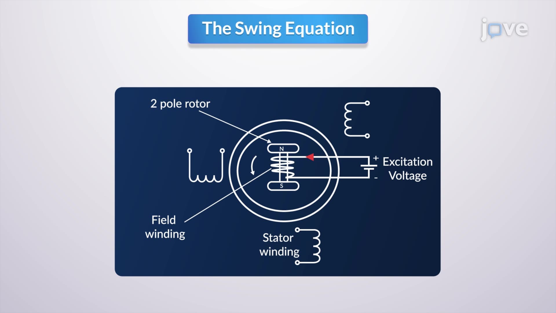
The magnetomotive force relationship explains why negative-sequence impedance differs from positive-sequence impedance. In normal operation, three-phase currents create a rotating magnetic field that aligns with the rotor. Negative-sequence currents generate a field rotating opposite to the rotor, creating additional losses and lower impedance. Zero-sequence currents, being identical in all phases, produce minimal net magnetic field, resulting in the smallest impedance value.
Related Micro-courses