Loading video…


 8 Concepts
 1.9K views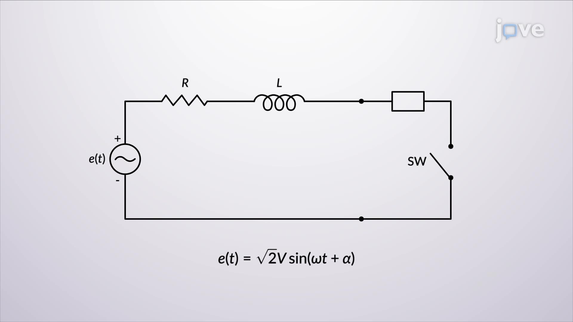

Video Summary: Series R L Circuit Transients Explained
When engineers at General Electric analyze power grid failures, they often encounter three phase short circuit unloaded scenarios that can damage equipment worth millions. Understanding how Series R L Circuit Transients Explained helps predict the massive current surges that occur when electrical faults happen in power systems. For instance, when lightning strikes a transmission line in Texas, the resulting short circuit creates both AC and DC current components that decay at different rates. Watch the full video on JoVE Coach to master this concept with expert-led visuals and step-by-step explanations.
Series R L Circuit Transients Explained forms the foundation for analyzing one of the most critical scenarios in electrical engineering: power system faults. When a three phase short circuit unloaded condition occurs-such as when tree branches contact high-voltage lines during storms-the resulting current behavior follows predictable patterns that can be modeled using simple RL circuit analysis.
During a three phase short circuit unloaded event, two distinct current components emerge simultaneously. The AC fault current, also called symmetrical current, represents the steady-state sinusoidal current that would flow if no transient effects existed. This current depends solely on the source voltage and circuit impedance, following Ohm's law principles students learn in AP Physics courses.
The DC offset current creates the most dangerous conditions. This exponentially decaying component arises because inductors resist sudden current changes, forcing the total current to start from zero (assuming no initial current). The DC component's magnitude depends critically on the source angle-the phase position when the fault occurs. Maximum DC offset happens when the source angle equals θ + π/2, creating the most severe fault conditions power engineers must design against.
The exponential decay of DC offset current follows the time constant τ = L/R, where L represents total system inductance and R represents total resistance. This relationship appears frequently on college electrical engineering exams, particularly in circuits courses. Higher L/R ratios-common in large power transformers at facilities like Hoover Dam-produce longer decay times and more sustained fault currents.
Understanding these transients proves essential for protective relay coordination in US power grids. For example, when Pacific Gas & Electric designs circuit breakers for California's transmission network, engineers must account for asymmetrical fault currents that can exceed symmetrical values by factors of 1.5 to 2.0 during the first few cycles. The asymmetry factor calculation-combining RMS AC current with maximum DC offset effects-determines proper breaker ratings and clearing capabilities.
Related Micro-courses