Loading subject page…


1,932 views

Video Summary: What are Per Unit Sequence Models
When a massive power grid failure struck Texas in February 2021, engineers relied on fault types analysis to identify system vulnerabilities and restore electricity to millions. Per unit sequence models are essential mathematical tools that help electrical engineers understand how different fault types behave in three-phase power systems, from transformers in local substations to transmission lines spanning entire states. These models simplify complex calculations by representing positive, negative, and zero-sequence components in standardized units. Watch the full video on JoVE Coach to master this concept with expert-led visuals and step-by-step explanations.
Per unit sequence models form the backbone of modern electrical fault analysis, transforming complex three-phase system calculations into manageable single-phase equivalent circuits. These mathematical representations are crucial for understanding how different types of fault types propagate through power networks, from residential distribution systems to major transmission infrastructure.
Every three-phase electrical system can be decomposed into three fundamental components. The positive sequence represents normal, balanced operation where all three phases carry equal currents with 120-degree phase separation. The negative sequence indicates unbalanced conditions, such as single-phase loads or asymmetrical faults. The zero sequence emerges during ground faults or other disturbances where current flows through neutral or ground paths.
In practical terms, when a tree falls on a power line in suburban Atlanta, creating a single line-to-ground fault, engineers use these sequence components to calculate fault currents and determine appropriate protective relay settings. The AP Physics C exam often tests students' understanding of these concepts through transformer equivalent circuit problems.
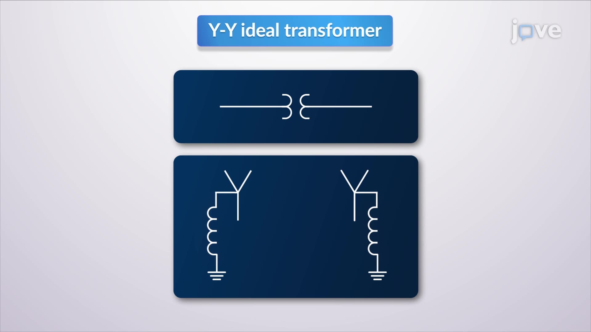
Y-Y transformers with neutral grounding present unique characteristics in sequence analysis. Under balanced conditions (positive or negative sequence), these transformers behave like simple single-phase units because neutral currents cancel out. However, zero-sequence currents combine algebraically, flowing through the neutral impedance and creating voltage drops that affect system performance.
Delta-delta transformers offer different advantages. Since delta windings have no neutral connection, zero-sequence currents cannot flow through the transformer, effectively blocking ground fault currents. This characteristic makes them valuable in industrial applications where fault isolation is critical. Major manufacturing facilities across the Midwest commonly employ delta-delta transformers for this reason.
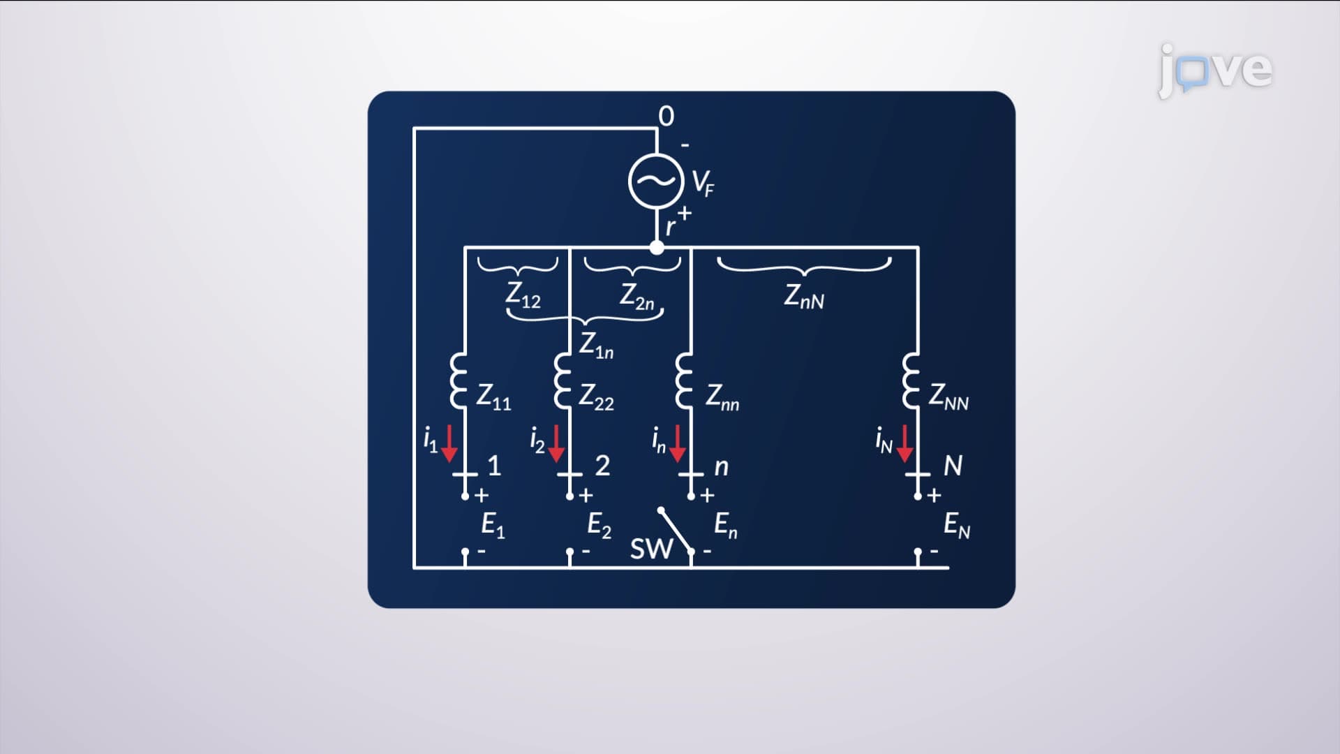
Three-winding transformers, common in utility substations from California to New York, require special modeling techniques. Engineers create equivalent circuits by connecting three single-phase transformers with common apparent power bases and proportional voltage bases. This approach simplifies calculations while maintaining accuracy for fault studies and protection coordination.
College electrical engineering programs, including those at Purdue University and Georgia Tech, emphasize these concepts because they directly apply to professional practice. Students preparing for the Fundamentals of Engineering (FE) exam encounter numerous problems involving per unit calculations and sequence component analysis.
Related Micro-courses