Loading subject page…


1,932 views

Video Summary: What Is Bus Impedance Matrix
When a massive electrical fault hits the Texas power grid during a winter storm, engineers need to predict exactly how much current will surge through each transmission line to prevent catastrophic failures. Circuit breaker and fuse selection depends on understanding the Bus Impedance Matrix, a powerful mathematical tool that calculates fault currents in complex power systems. This matrix reveals how electrical disturbances at one location affect voltages and currents throughout the entire network, making it essential for protecting infrastructure like the substations serving Houston's medical center. Watch the full video on JoVE Coach to master this concept with expert-led visuals and step-by-step explanations.
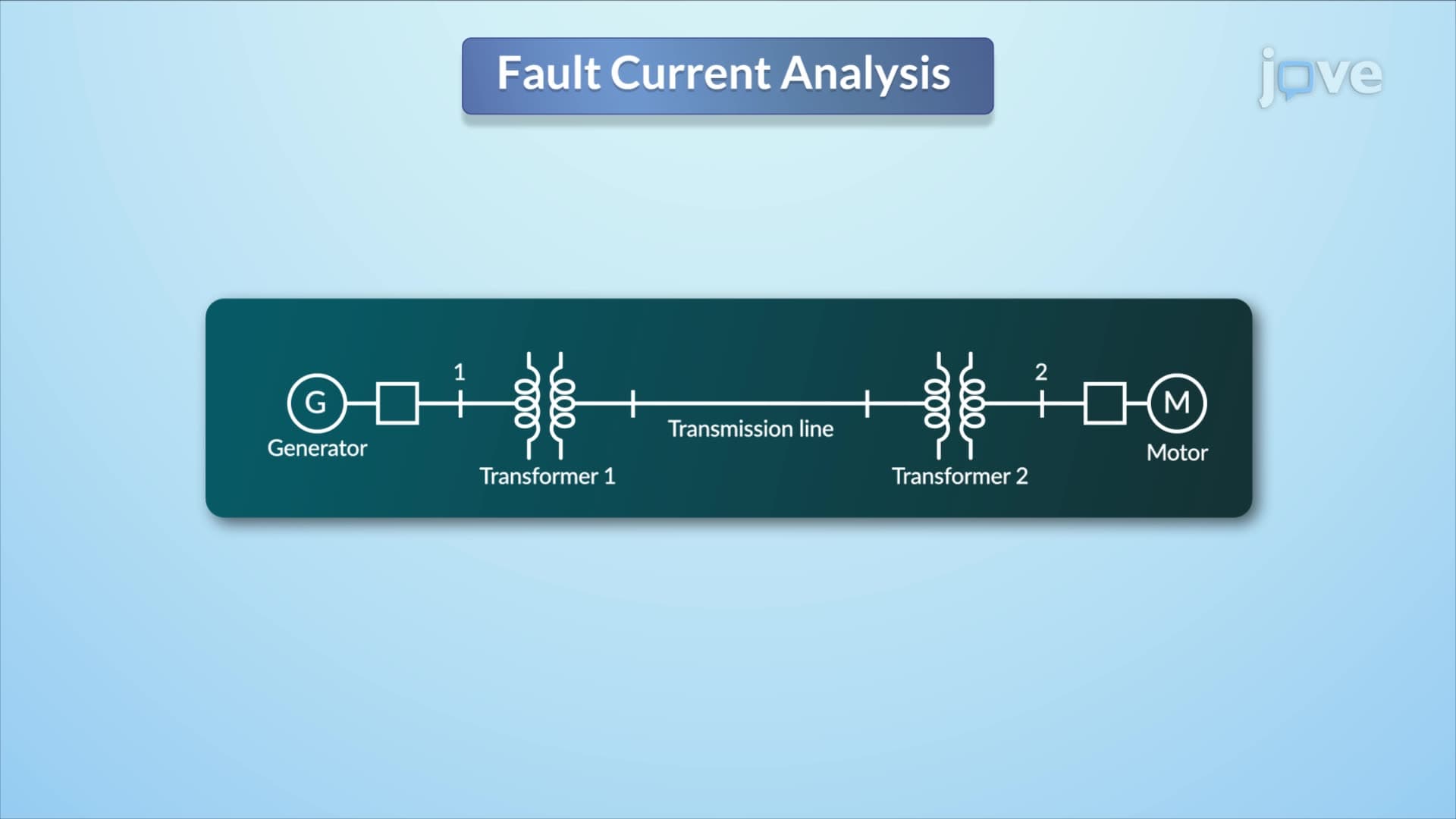
The Bus Impedance Matrix serves as the mathematical backbone for analyzing electrical faults in power transmission systems. Unlike simple circuit analysis you might encounter in introductory physics, this matrix approach handles the complexity of interconnected power networks where a fault at one location affects the entire system. Think of it like analyzing traffic flow disruptions, when Interstate 95 closes near Washington D.C., traffic patterns change throughout the entire Eastern corridor.
In power systems engineering, the matrix captures how impedances (opposition to current flow) between different buses (connection points) influence fault current distribution. This concept frequently appears in advanced electrical engineering coursework and professional engineering exams, where students must demonstrate understanding of both theoretical principles and practical applications.
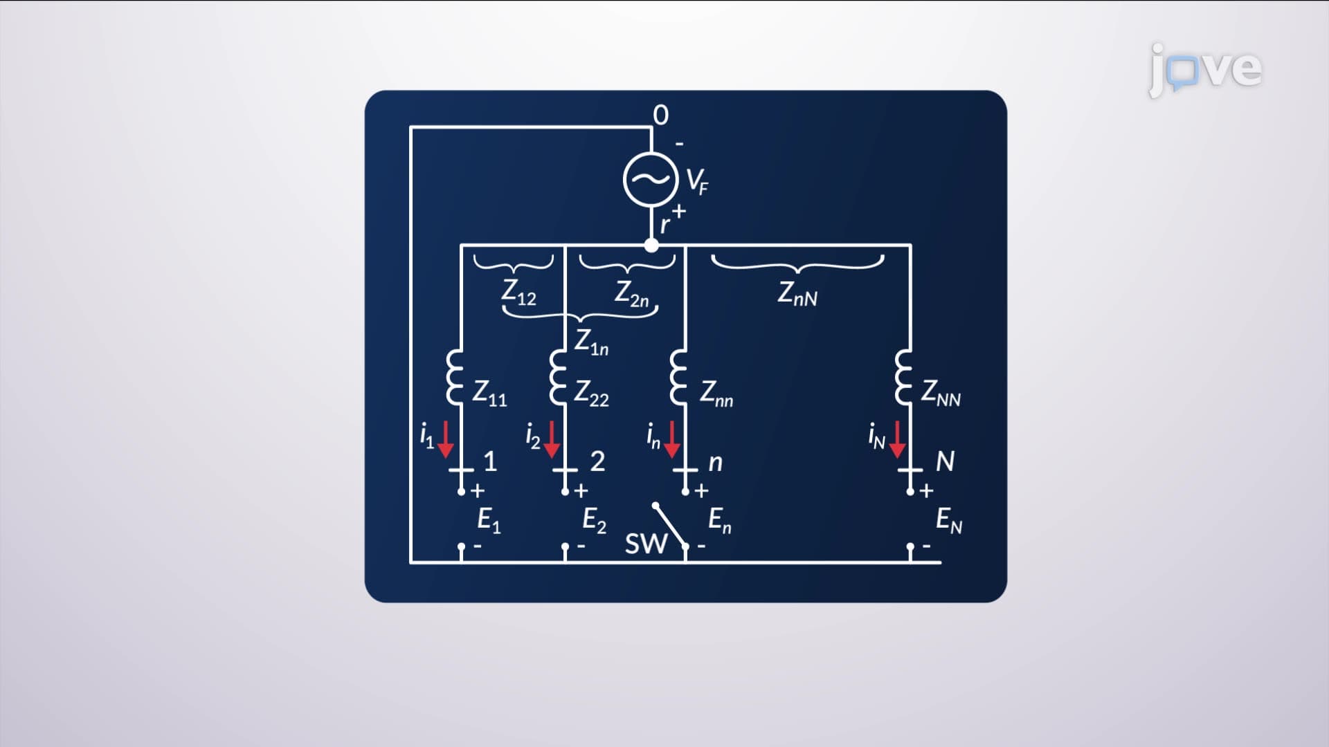
The superposition method breaks complex fault analysis into manageable components by examining two distinct circuits. The first circuit eliminates all machine voltage sources except at the fault location, creating a simplified model where only the fault-driving voltage remains active. This approach mirrors the superposition principle you've likely encountered in AP Physics, but applies it to industrial-scale power systems.
Circuit breaker and fuse selection tutorial applications rely heavily on this analysis because protection equipment must respond to the actual fault currents, not theoretical maximums. For instance, when Pacific Gas & Electric designs protection schemes for California's transmission grid, engineers use these calculations to ensure circuit breakers can safely interrupt fault currents without causing wider blackouts.
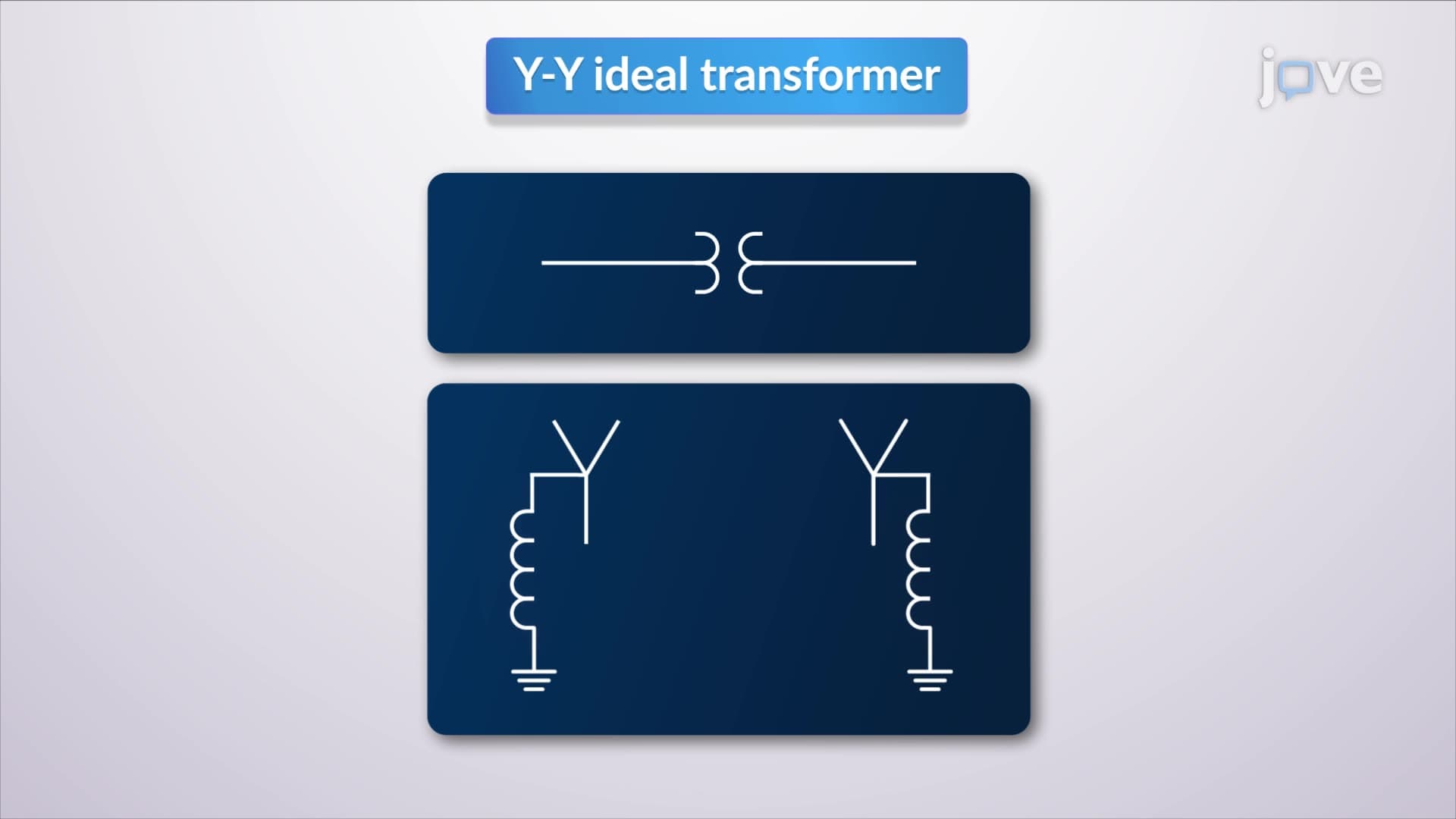
The positive-sequence network representation simplifies three-phase system analysis by focusing on balanced conditions. This mathematical technique transforms complex three-phase calculations into single-phase equivalent circuits, making the math more tractable while maintaining accuracy. Students preparing for the Fundamentals of Engineering (FE) exam encounter this concept extensively in the electrical and computer engineering sections.
How circuit breaker and fuse selection works becomes clearer when you understand that protection devices respond to sequence components differently. The positive-sequence impedance matrix reveals the primary fault current paths, helping engineers size protective equipment appropriately. Major utilities like ConEd in New York rely on these calculations to coordinate protection schemes across their vast interconnected network.
Modern power system protection requires precise fault current calculations to ensure reliable operation. The Bus Impedance Matrix enables engineers to predict fault behavior before installing expensive equipment, reducing both costs and reliability risks. This circuit breaker and fuse selection overview demonstrates why theoretical understanding translates directly to professional practice, whether you're designing residential distribution panels or industrial substations serving semiconductor fabrication facilities in Silicon Valley.
Related Micro-courses