Loading video…


 12 Concepts
 16.2K views


Video Summary: Problem Solving with Mohr S Circle for Moments of Inertia
Ever wondered how engineers determine if a bridge beam can handle the stress of heavy traffic without complex calculations? Problem-solving with Mohr's Circle for moments of inertia transforms tedious mathematical computations into elegant graphical solutions. This powerful technique helps structural engineers analyze steel I-beams used in skyscrapers like New York's One World Trade Center, where understanding principal moments of inertia is critical for safety. The method visualizes how cross-sectional properties change with orientation, making complex beam analysis more intuitive. Watch the full video on JoVE Coach to master this concept with expert-led visuals and step-by-step explanations.
Problem-solving with Mohr's Circle for moments of inertia represents one of structural engineering's most elegant analytical tools. Developed by German engineer Otto Mohr in 1882, this graphical method transforms abstract mathematical concepts into visual solutions that engineers worldwide rely on daily. When analyzing structural members like the steel beams supporting the Golden Gate Bridge or the concrete columns in the Hoover Dam, engineers need to understand how cross-sectional properties behave under different orientations.
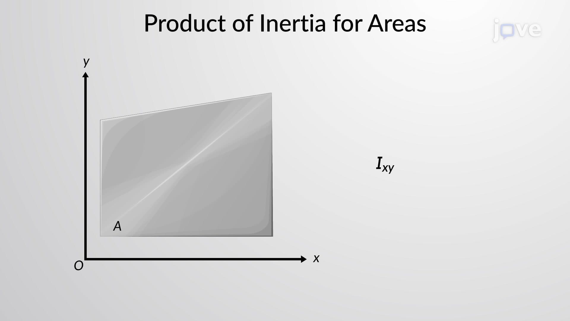
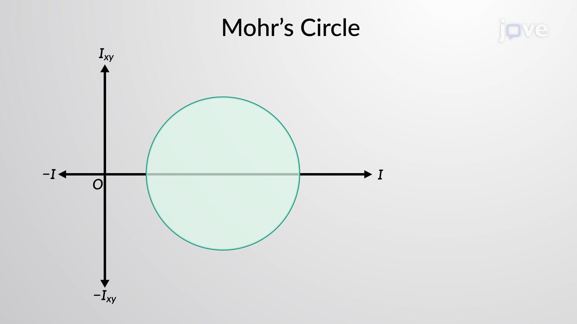
The construction process begins with known values: moments of inertia about rectangular x and y axes (Ix and Iy) and the product of inertia (Ixy). These values are plotted on a specialized coordinate system where the horizontal axis represents moments of inertia and the vertical axis represents products of inertia. The circle's center lies at ((Ix + Iy)/2, 0), representing the average of the rectangular moments.
The circle's radius equals √[((Ix - Iy)/2)² + (Ixy)²], incorporating both the difference in rectangular moments and the product of inertia. This radius determines the magnitude of principal moments, which represent the absolute maximum and minimum second moments of area for any given cross-section.
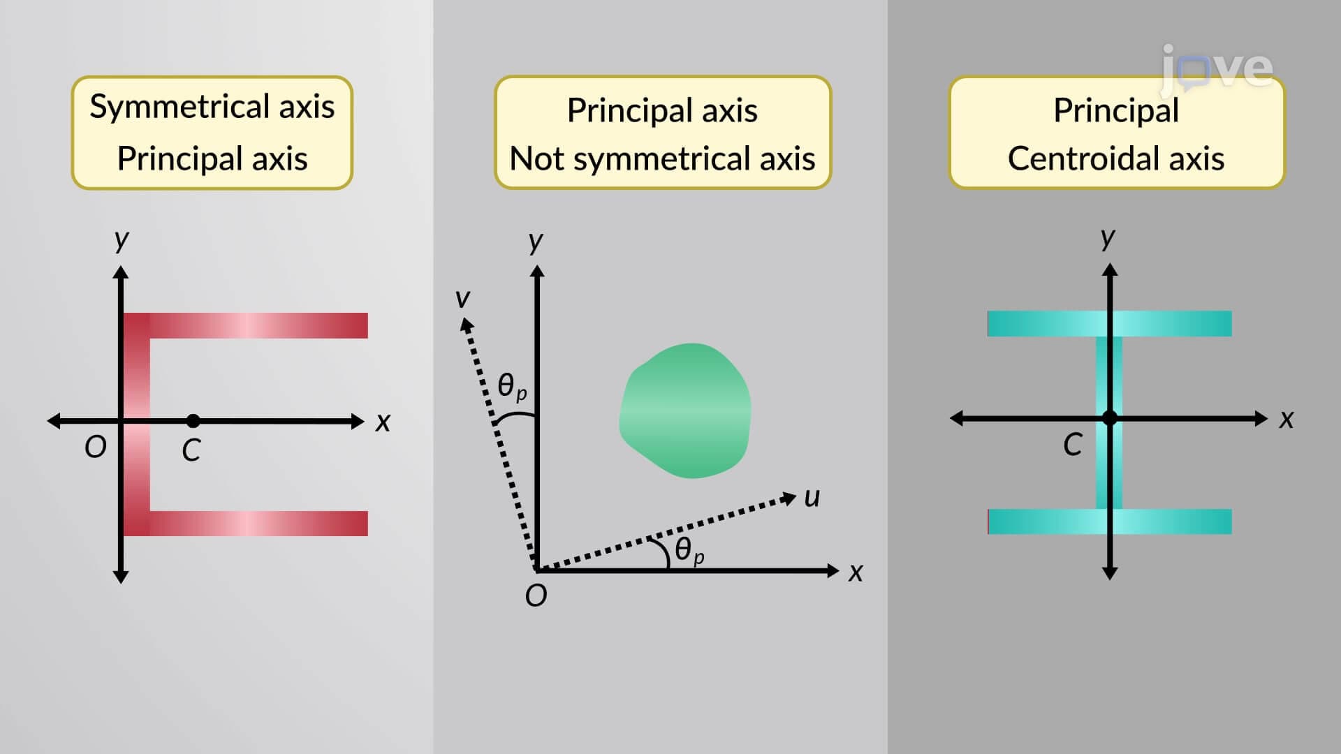
The intersection points of Mohr's circle with the horizontal axis reveal the principal moments of inertia: Imax = Icenter + radius and Imin = Icenter - radius. These values are crucial for structural design because they represent the extreme conditions under which a beam will experience bending. The angle to the principal axis equals half the angle measured on Mohr's circle, following the fundamental relationship between physical rotation and graphical representation.
In practice, this concept appears frequently in AP Physics C mechanics problems and college-level statics courses. Students studying for the Fundamentals of Engineering (FE) exam encounter Mohr's circle applications in structural analysis sections, where understanding principal moments determines whether designs meet safety factors required by building codes.
Consider the design of aircraft wing spars used in Boeing 737 manufacturing. Engineers must optimize cross-sectional shapes to minimize weight while maximizing bending resistance. Mohr's circle analysis reveals the optimal orientation for composite fiber layers, ensuring maximum strength along principal axes. Similarly, in earthquake-resistant building design across California, structural engineers use this method to analyze how building columns respond to multi-directional seismic forces, ensuring structures can withstand both vertical loads and lateral earthquake motions.
Related Micro-courses