Loading subject page…

- Electrical Engineering
- Diagrams and Signal Flow Graphs
- Relation between Mathematical Equations and Block Diagrams
Micro-course: Diagrams and Signal Flow Graphs
4,809 views
Learn key concepts and earn your certificate.
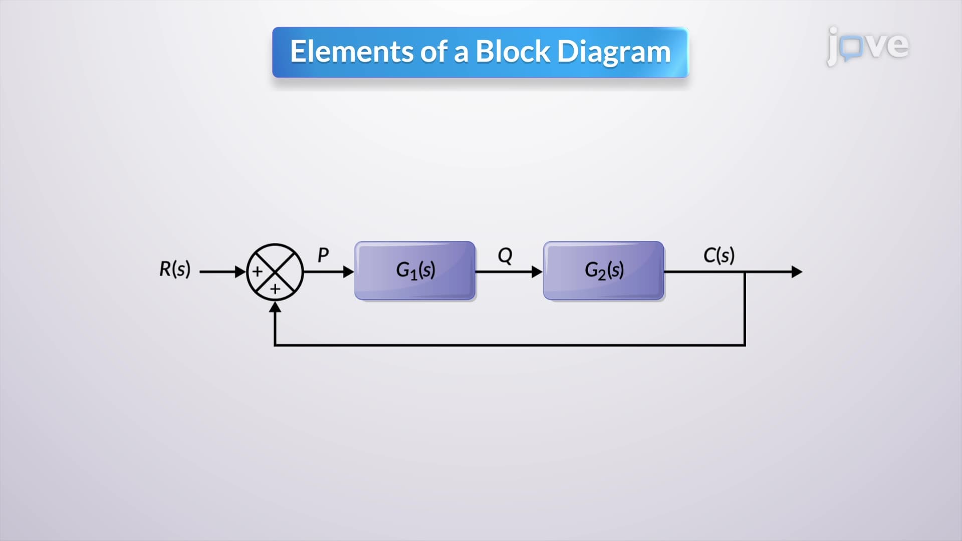

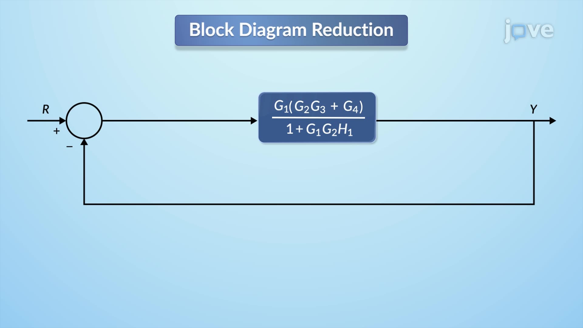

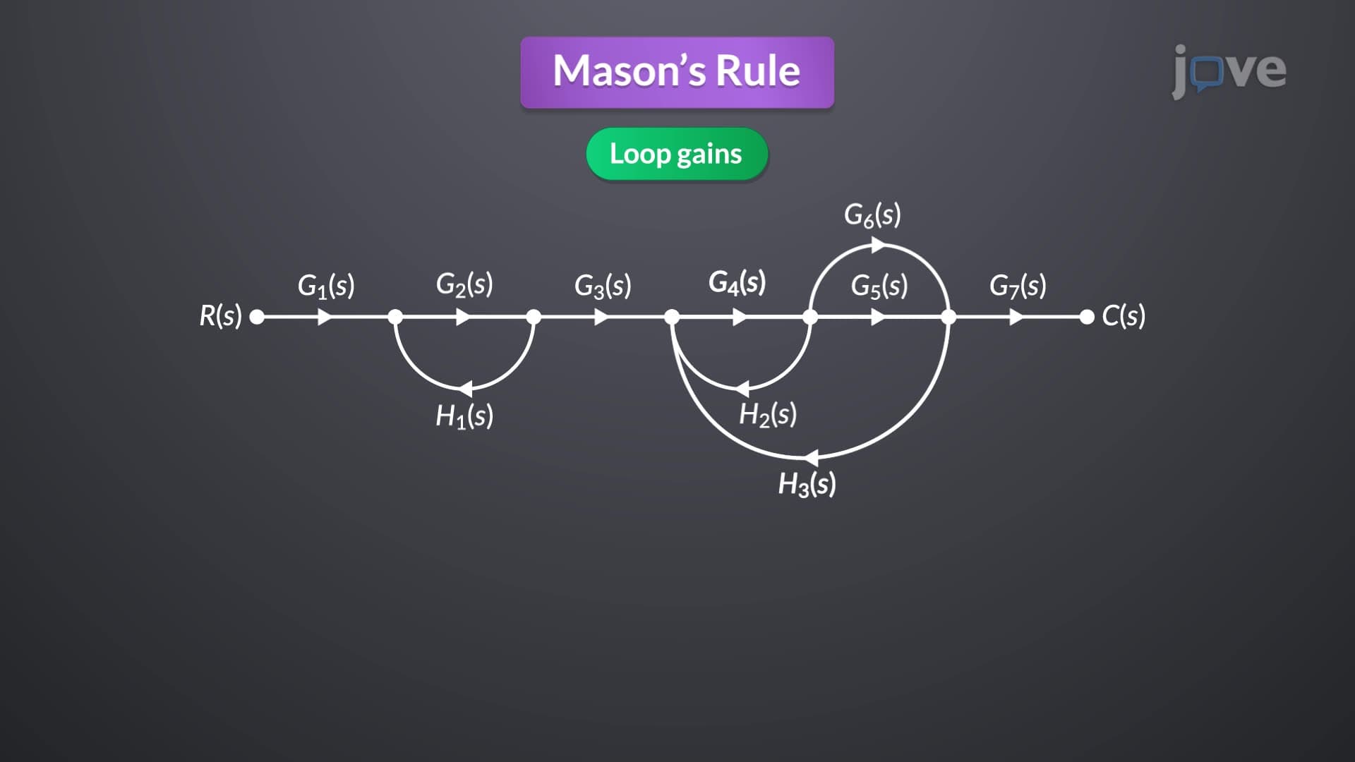
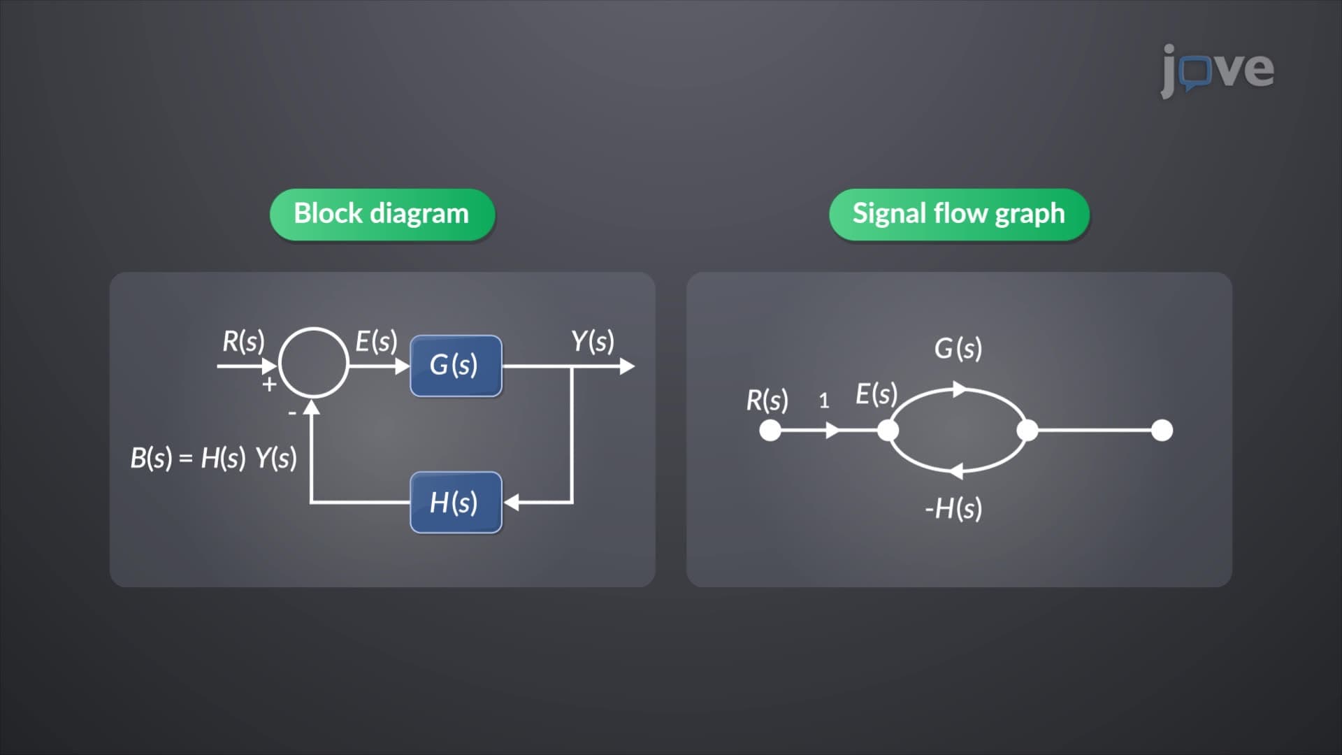
Relation between Mathematical Equations and Block Diagrams

00:00
01:20
Video Summary: Relation Between Mathematical Equations and Tutorial
Ever wondered how NASA engineers analyze spacecraft vibrations during launch? Block diagram reduction transforms complex spring-mass-damper differential equations into simplified visual representations that reveal system behavior at a glance. Like analyzing the suspension system in a Ford F-150 pickup truck, engineers use the relation between mathematical equations and tutorial methods to convert second-order differential equations into manageable block diagrams through Laplace domain transformation. Watch the full video on JoVE Coach to master this concept with expert-led visuals and step-by-step explanations.
- Understand the relation between mathematical equations and tutorial approaches for converting differential equations into block diagram representations
- Identify how Laplace domain transformation simplifies second-order differential equations under zero initial conditions
- Analyze the step-by-step process of isolating outputs and interpreting signals as transfer function blocks
- Apply block diagram reduction techniques to represent spring-mass-damper systems visually
- Recognize how internal variables like acceleration and velocity integrate through 1/s operations in the Laplace domain
- Evaluate different block diagram configurations and choose optimal representations for system analysis
- Compare original differential equations with their simplified block diagram equivalents
- Explore transfer function derivation through systematic block manipulation and feedback loop simplification
Understanding the Relation Between Mathematical Equations and Tutorial Methods
Block diagram reduction serves as a powerful bridge between complex mathematical formulations and intuitive visual understanding. When engineering students at institutions like MIT or Georgia Tech encounter second-order differential equations describing dynamic systems, the mathematical complexity can be overwhelming. The relation between mathematical equations and tutorial visualization transforms abstract calculus into concrete, manipulable components.
Laplace Domain Transformation Fundamentals
The transformation process begins with converting time-domain differential equations into the Laplace domain, where differentiation becomes multiplication and integration becomes division by 's'. For a typical spring-mass-damper system found in automotive suspension design, the second-order equation m(d²x/dt²) + c(dx/dt) + kx = F(t) becomes (ms² + cs + k)X(s) = F(s) in the Laplace domain. This algebraic manipulation eliminates the complexity of solving differential equations directly.
Students preparing for AP Physics C or college-level controls courses benefit tremendously from this visual approach. The block diagram reduction definition encompasses the systematic process of representing mathematical relationships as interconnected blocks, each performing specific operations on input signals to produce outputs.
Block Diagram Construction and Simplification
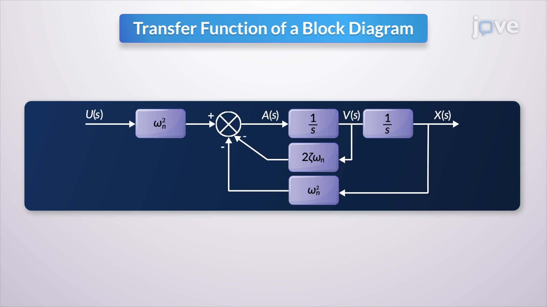
What is block diagram reduction in detail involves multiple systematic steps. First, engineers isolate the output variable by rearranging the transformed equation. Each mathematical operation becomes a distinct block: multiplication by constants, integration (1/s), and summation at junction points. For aerospace applications at companies like Lockheed Martin, engineers routinely apply these techniques to analyze aircraft control systems.
The beauty of block diagram reduction basics lies in the modular approach. Internal variables like acceleration and velocity emerge naturally through successive integration operations. When 1/s represents integration, the acceleration signal passes through one integrator to yield velocity, then through another to produce displacement. This visual representation makes physical intuition immediately apparent.
Transfer Function Derivation Through Block Manipulation
The final step involves algebraic manipulation of the block diagram to derive the system's transfer function. By moving blocks and simplifying feedback loops, engineers obtain the ratio of output to input in the Laplace domain. This transfer function becomes invaluable for frequency response analysis, stability assessment, and controller design-skills essential for students pursuing engineering careers at companies like Tesla or SpaceX.
Frequently Asked Questions
The relation between mathematical equations and tutorial methods provides a systematic approach to convert complex differential equations into visual block diagrams. This transformation makes mathematical relationships intuitive by representing each operation as a distinct block, enabling engineers to analyze system behavior through visual inspection rather than complex calculus.
Block diagram reduction definition refers to the systematic process of simplifying interconnected block representations of dynamic systems into equivalent, more manageable forms. The technique transforms mathematical equations into visual components where each block performs specific operations like integration, multiplication, or summation on input signals.
AP Physics C exams typically test block diagram reduction through problems involving mechanical oscillators or electrical circuits. Students must demonstrate understanding of Laplace transforms, transfer functions, and the ability to convert differential equations into block diagram form, often worth 10-15 points on the mechanics or electricity sections.
While MCAT doesn't directly test block diagram reduction, the underlying mathematical reasoning appears in physiology questions about feedback systems, homeostasis, and signal processing. Understanding how biological systems respond to inputs through interconnected processes mirrors the block diagram approach to system analysis.
At Boeing, engineers use block diagram reduction to analyze aircraft flight control systems, modeling how pilot inputs translate through hydraulic actuators to control surface movements. The technique helps design stable, responsive aircraft by visualizing complex multi-input, multi-output control systems as manageable block diagrams.
Block diagram reduction basics are accessible to high school students with solid algebra and basic calculus knowledge. The visual nature actually makes complex systems more understandable than pure mathematical approaches, especially when introduced through familiar examples like car suspension systems or audio equipment.
Focus on practicing with simple second-order systems first, then progress to more complex configurations. Draw diagrams by hand to reinforce understanding, work through complete examples from differential equation to final transfer function, and connect each mathematical step to its physical meaning in the system being analyzed.
Students should explore root locus analysis, Bode plots, and state-space representations next. These topics extend block diagram concepts into frequency domain analysis and modern control theory, essential for advanced engineering courses and careers in robotics, aerospace, or automotive control systems design.
Related Micro-courses
7 Concepts
10 Concepts