Loading subject page…


4,809 views

Video Summary: What are Elements of Block Diagrams
Ever wondered how NASA engineers model the Space Shuttle's complex control systems using simple boxes and arrows? The relation between mathematical equations and visual representations becomes crystal clear through block diagrams-powerful tools that transform complex system behaviors into understandable visual models. Consider Tesla's autopilot system, where sensors, processors, and actuators work together through precisely defined mathematical relationships. Understanding what are elements of block diagrams helps engineers design everything from home thermostats to Mars rovers. Watch the full video on JoVE Coach to master this concept with expert-led visuals and step-by-step explanations.
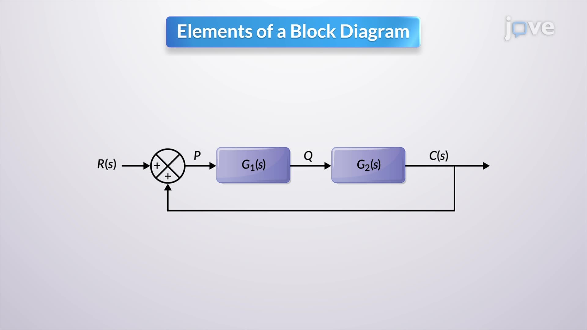
Block diagrams serve as the universal language of systems engineering, providing a visual roadmap for understanding complex relationships. The relation between mathematical equations and graphical representations becomes evident when we examine how each block contains specific mathematical functions. These diagrams transform abstract equations into intuitive visual models that engineers at companies like Boeing and General Electric use daily.
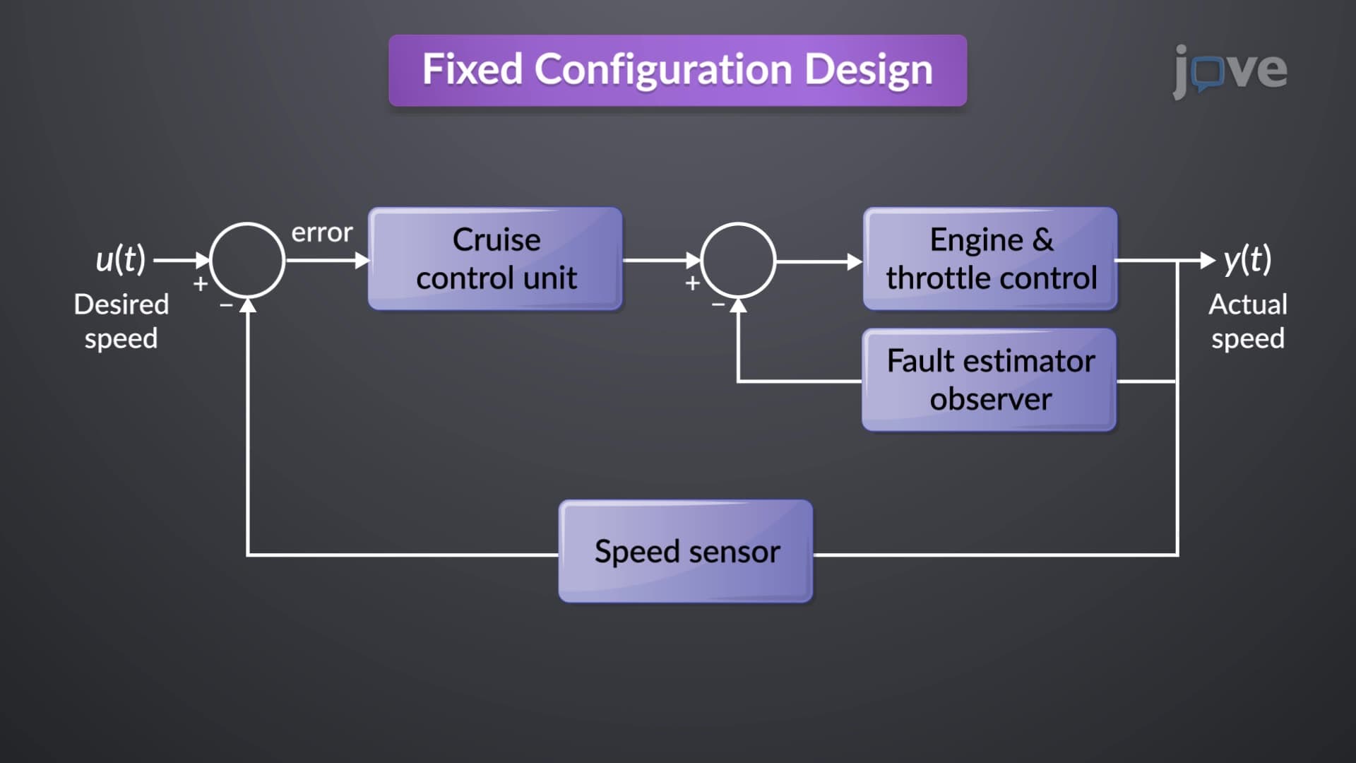
Comparators function as mathematical junction points where signals meet and interact. In a typical automotive cruise control system, the comparator receives two inputs: your desired speed (reference) and actual vehicle speed (feedback). The relation between mathematical equations and example scenarios shows how subtraction occurs: Error = Reference Speed - Actual Speed. This error signal then drives the throttle control system. For AP Physics students, understanding comparators helps solve complex circuit analysis problems involving operational amplifiers and control theory.
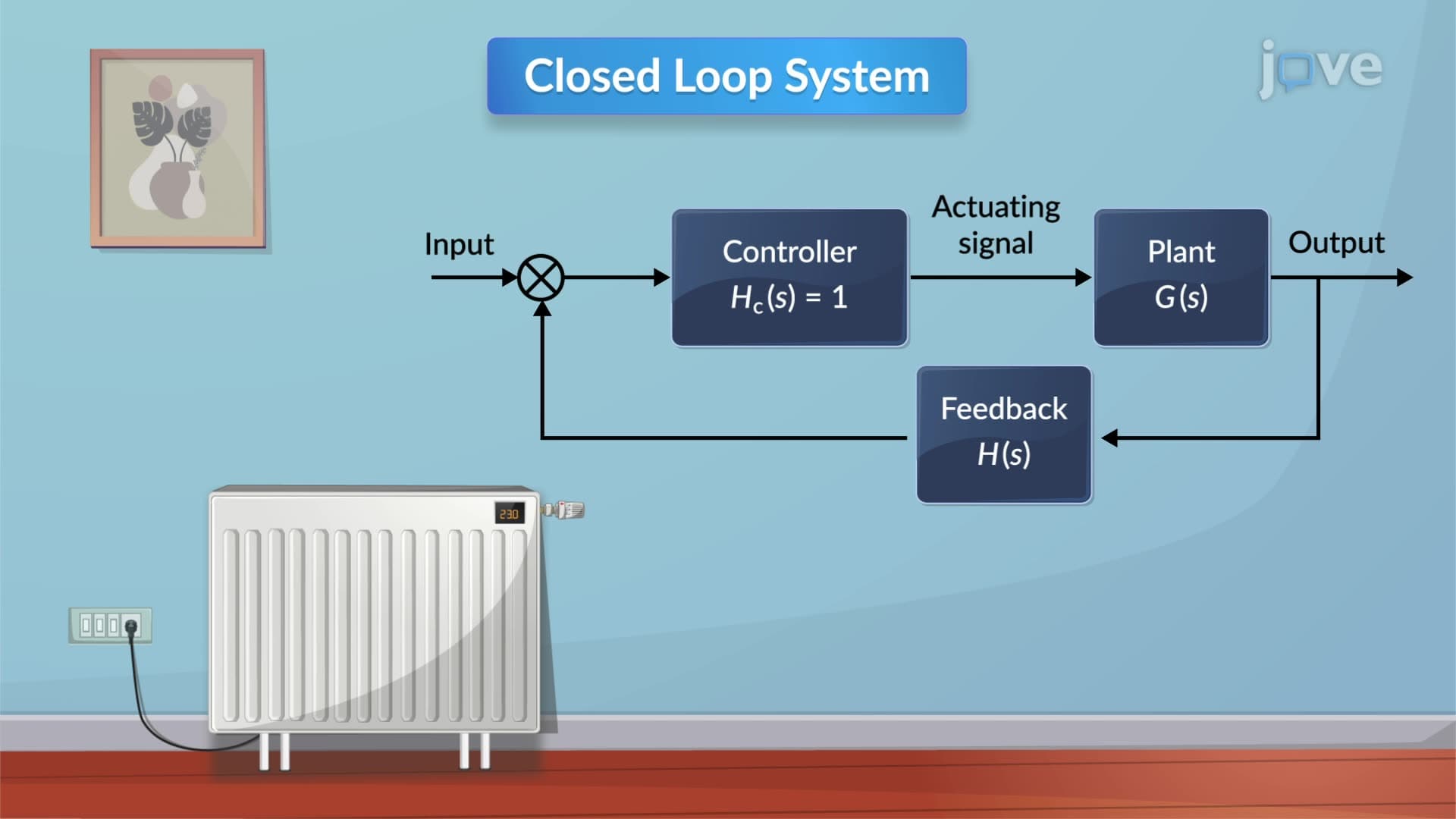
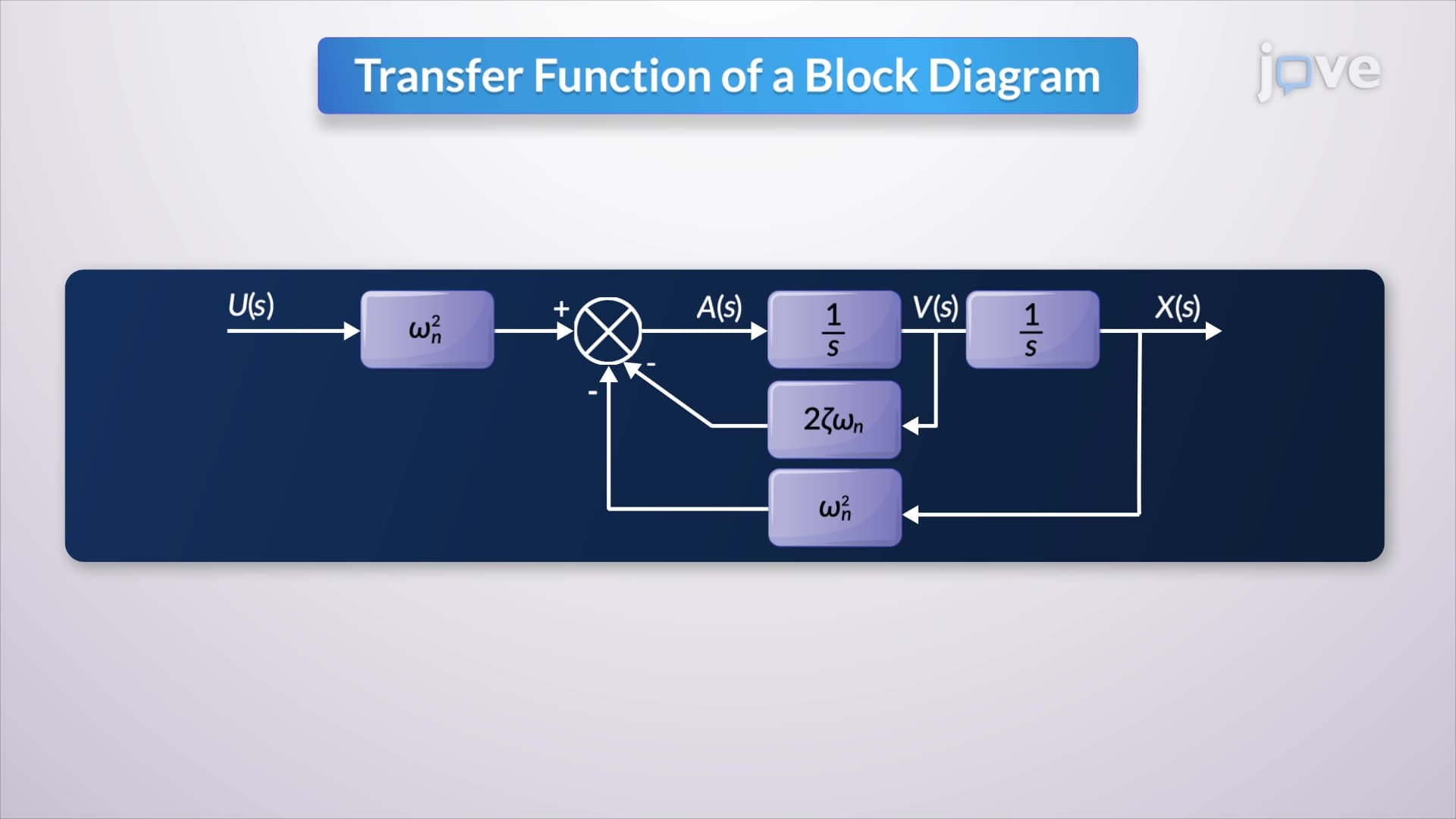
Transfer function blocks contain the core mathematical relationships governing system behavior. In the Laplace domain, these blocks represent H(s) functions that describe how inputs transform into outputs. Consider a building's HVAC system designed by Carrier Corporation-each zone's temperature control involves transfer functions relating heat input to temperature output. The relation between mathematical equations and step by step analysis reveals how engineers combine multiple transfer functions to predict system response, essential knowledge for SAT Subject Tests in Physics and college-level control systems courses.
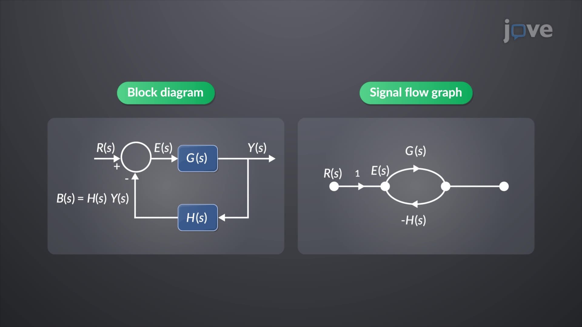
Feedback loops distinguish simple open-loop systems from sophisticated closed-loop control systems. NASA's attitude control systems on the International Space Station exemplify negative feedback-when the station drifts from desired orientation, sensors detect the error, and thrusters fire to correct the deviation. The relation between mathematical equations and overview of feedback systems shows how stability analysis using root locus and Bode plots ensures reliable operation. Students preparing for the MCAT encounter similar feedback concepts in biological homeostasis questions.
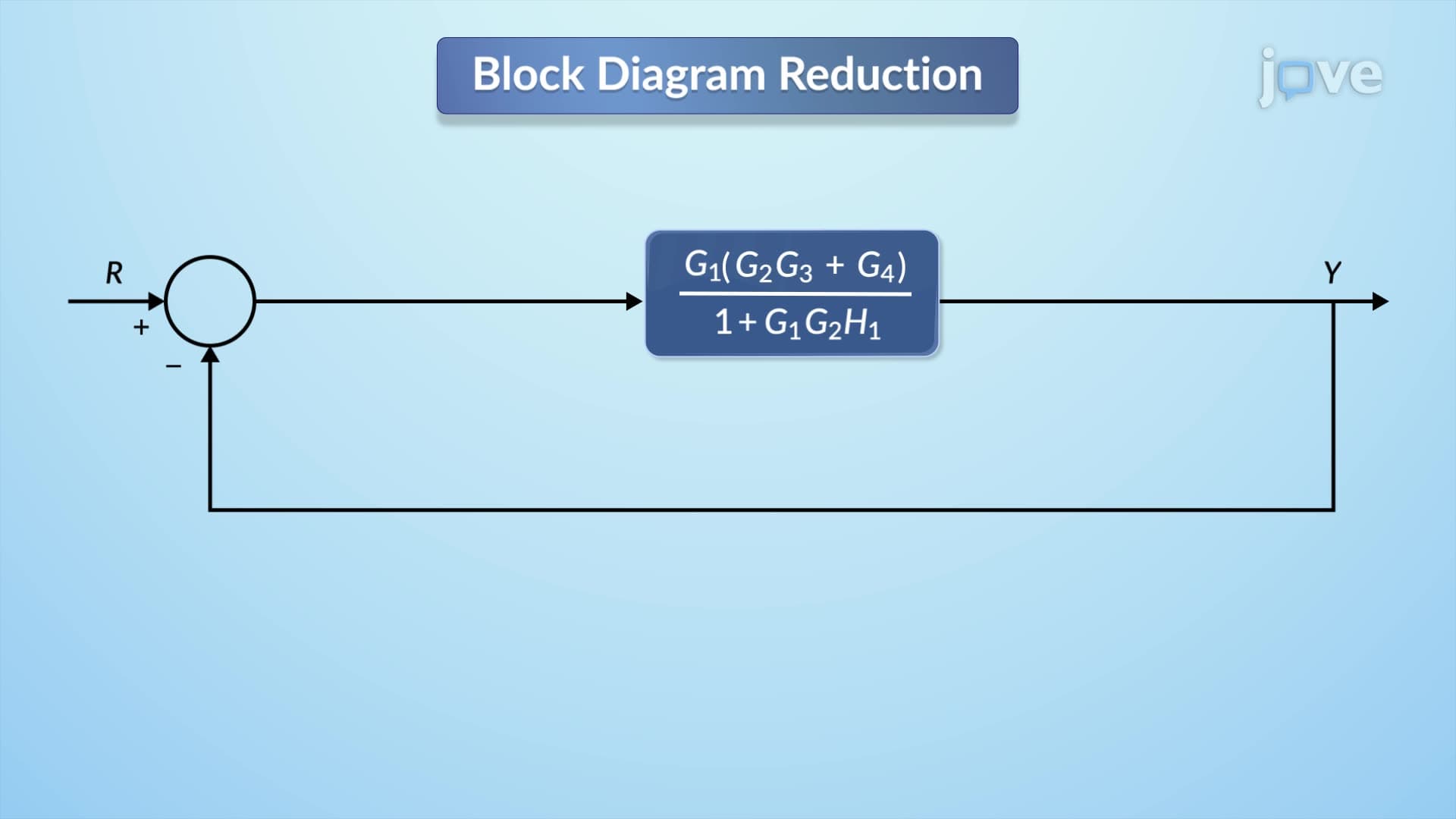
Real systems rarely consist of single blocks. Industrial processes combine elements in series (sequential processing) and parallel (simultaneous processing) configurations. Manufacturing plants like those operated by General Motors use series combinations for assembly line control and parallel combinations for redundant safety systems. Understanding these combinations helps solve complex transfer function problems common in engineering coursework and professional engineering (PE) exam preparations.
Related Micro-courses