Loading subject page…


4,809 views

Video Summary: What Is Block Diagram Reduction
Ever wonder how engineers at Boeing simplify complex flight control systems with hundreds of components into manageable designs? Multi input and multi variable systems require sophisticated analysis techniques, and block diagram reduction is the key method that transforms intricate control networks into single, equivalent blocks. This mathematical process involves strategically moving branch points and comparators while preserving system functionality. For example, NASA uses these techniques to model spacecraft attitude control systems during mission planning. Watch the full video on JoVE Coach to master this concept with expert-led visuals and step-by-step explanations.
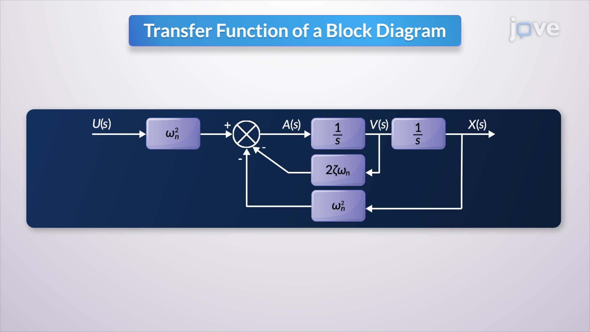
Block diagram reduction is a systematic mathematical technique used to simplify complex control systems by combining multiple interconnected blocks into a single equivalent block. This process is particularly crucial when dealing with multi input and multi variable systems, where traditional analysis methods become unwieldy. Engineers at companies like General Electric and Lockheed Martin rely on these techniques to design everything from power plant control systems to fighter jet autopilots.
The foundation of effective block diagram reduction lies in understanding how to relocate branch points and comparators without altering system behavior. When working with multi input and multi variable systems, engineers must carefully track signal paths and mathematical relationships. A branch point represents a signal split, while comparators handle signal addition or subtraction. The key principle is maintaining signal equivalence, the mathematical output must remain identical before and after any relocation.
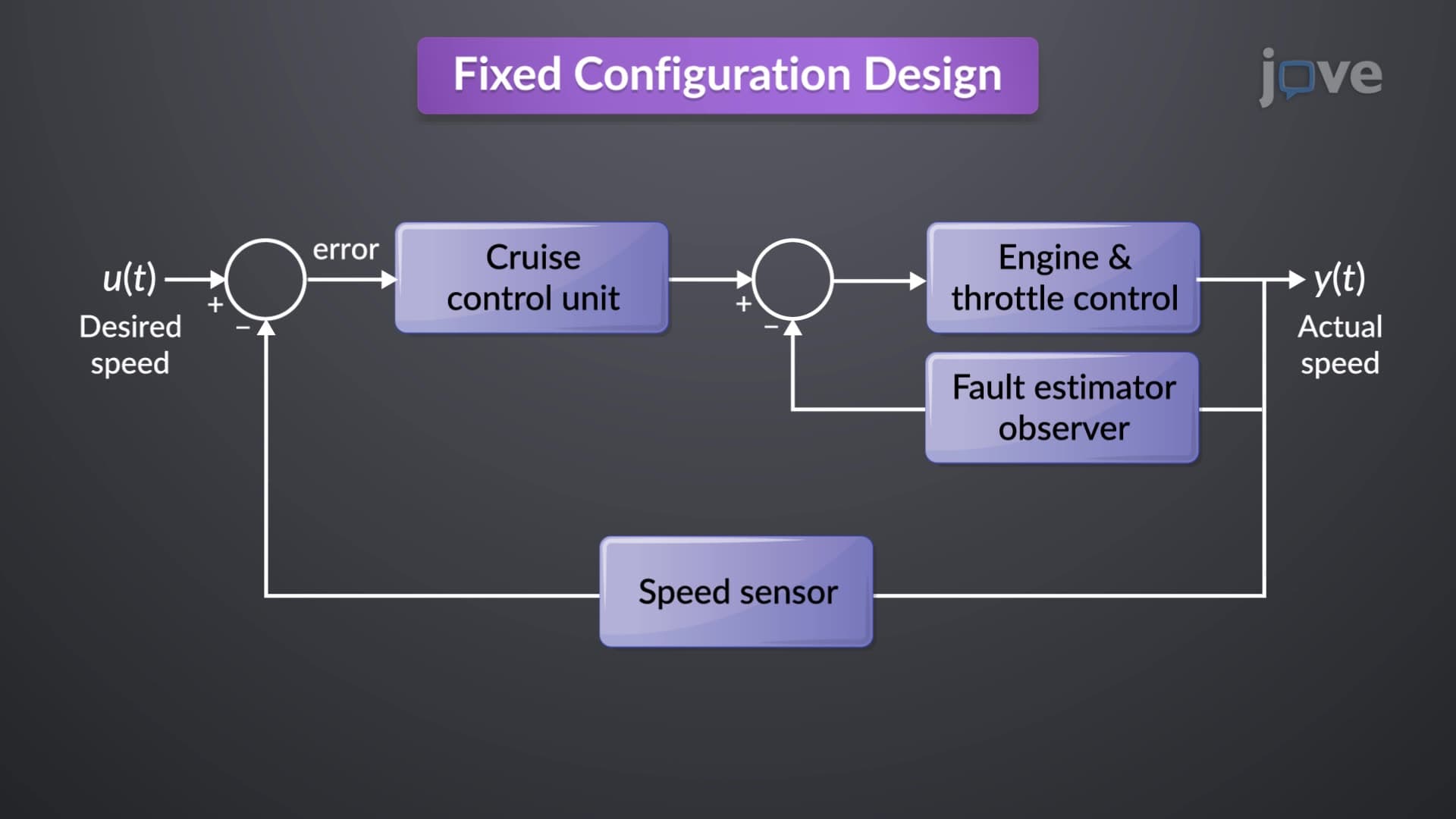
For students preparing for AP Physics or college-level control systems courses, mastering this concept requires understanding that each move must preserve the transfer function. Consider an automotive cruise control system: the original complex diagram showing throttle position, speed sensors, and engine controls can be reduced to a single block representing the overall speed-to-throttle relationship.
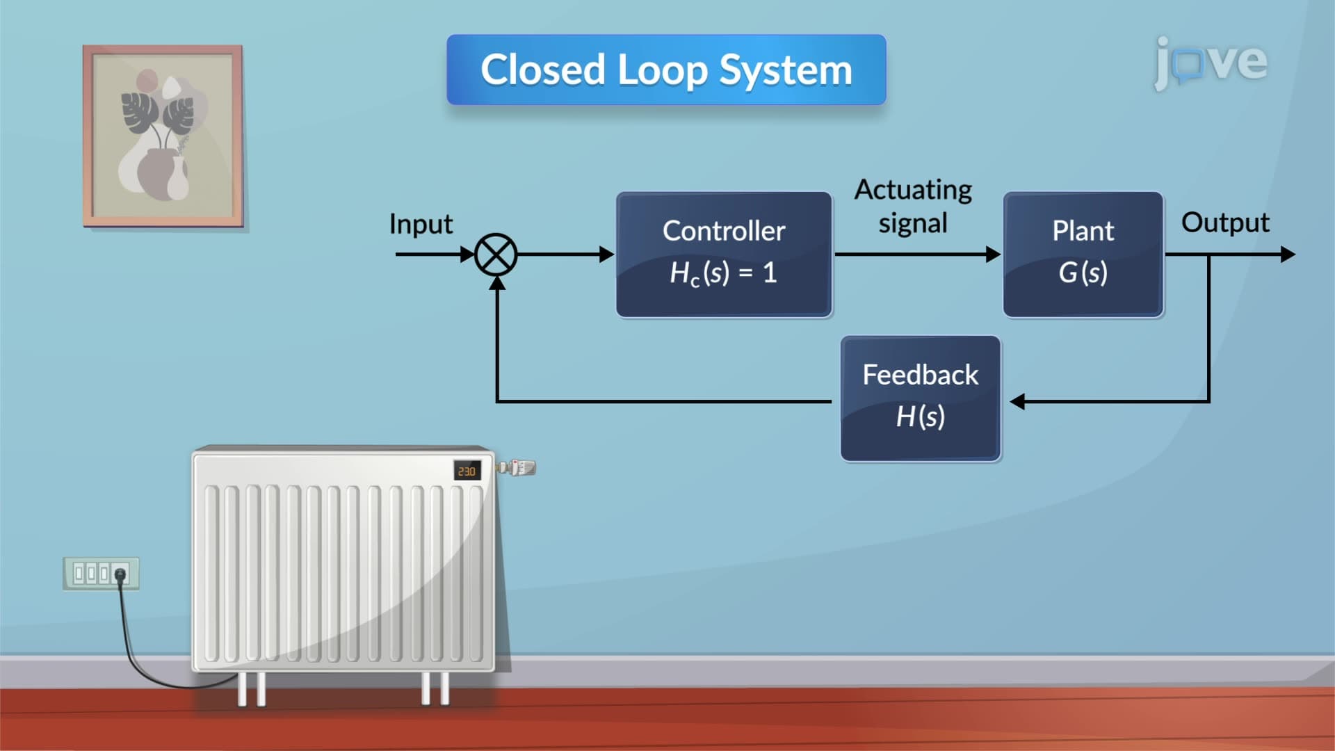
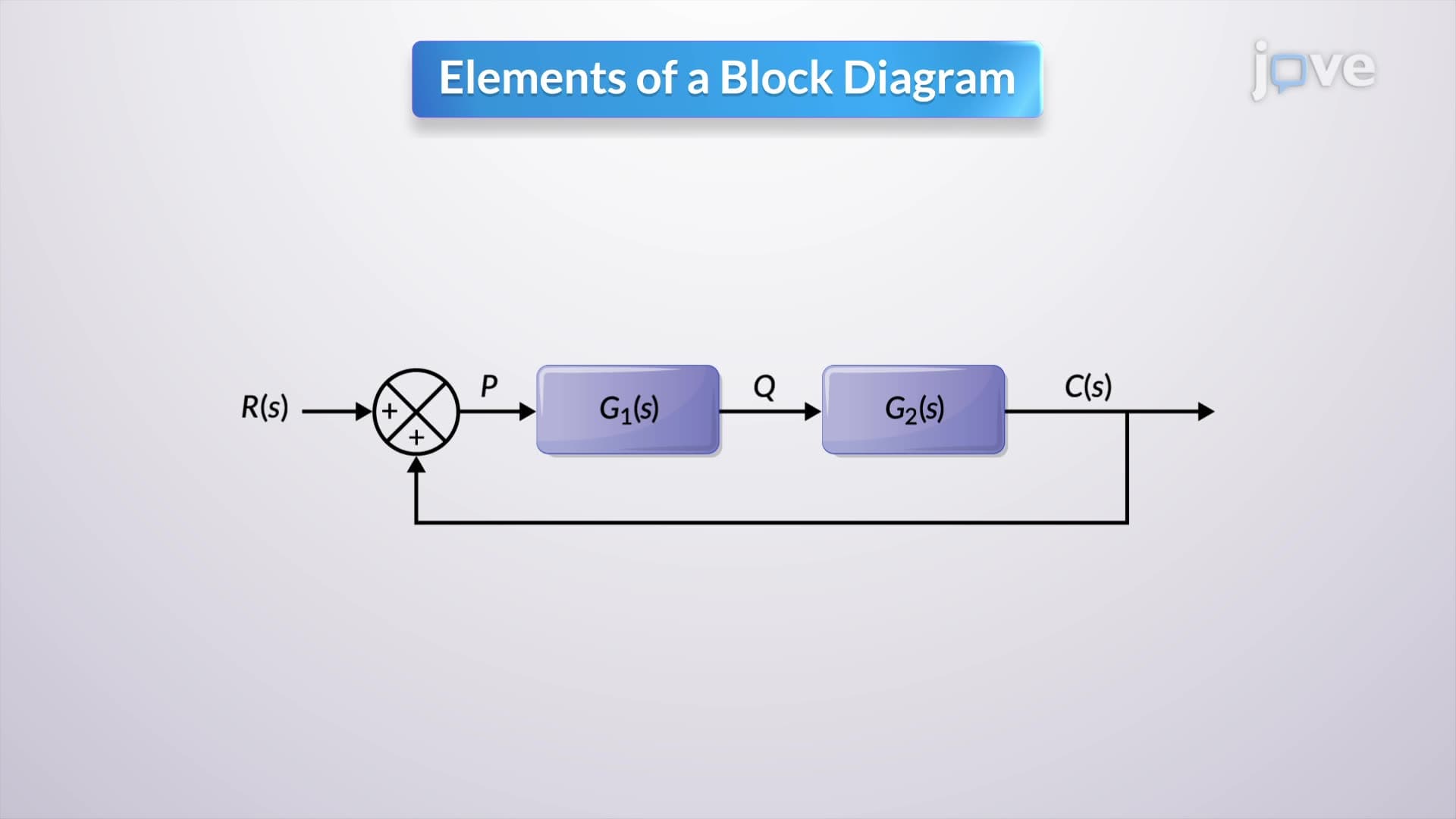
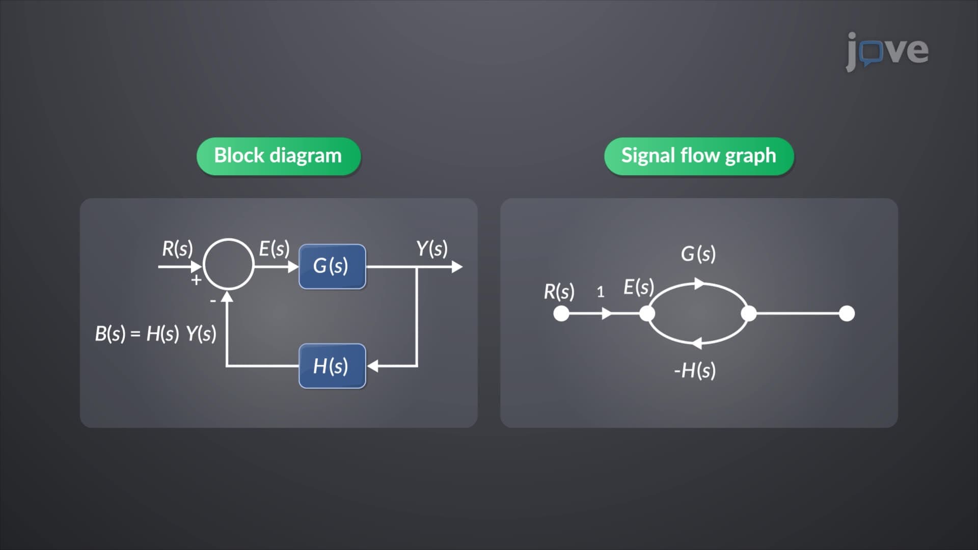
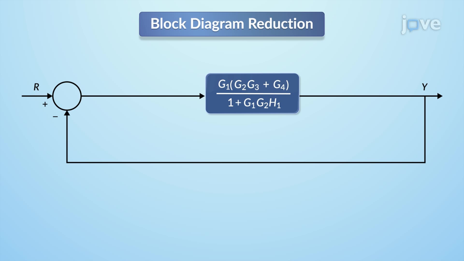
Once components are properly positioned, the next phase involves combining multiple blocks using algebraic rules. Series blocks multiply their transfer functions (G1 × G2), while parallel blocks add them (G1 + G2). Feedback loops follow the formula G/(1 ± GH), where G is the forward path and H is the feedback path. These rules form the mathematical backbone that students encounter in engineering coursework and standardized tests.
Understanding multi input and multi variable systems through block diagram reduction appears frequently in MCAT physics sections, AP Physics exams, and college engineering assessments. Students studying for these exams should focus on step-by-step reduction procedures and transfer function calculations. Industrial applications include manufacturing automation systems, where complex sensor networks and actuator controls are simplified for design optimization and troubleshooting.
Related Micro-courses