Loading subject page…

- Mechanical Engineering
- Planar Kinematics of a Rigid Body
- Relative Motion Analysis using Rotating Axes
Micro-course: Planar Kinematics of a Rigid Body
6,864 views
Learn key concepts and earn your certificate.







Relative Motion Analysis using Rotating Axes

00:00
01:25
Video Summary: Relative Motion Analysis Using Rotating Axes Explained
Ever wondered how NASA engineers calculate spacecraft trajectories when multiple objects are spinning and moving simultaneously? Relative motion analysis using rotating axes helps solve these complex problems by breaking down motion into manageable components. This technique is essential for understanding how Boeing 747 landing gear retracts while the aircraft banks during approach to LAX airport. Watch the full video on JoVE Coach to master this concept with expert-led visuals and step-by-step explanations.
- Understand the fundamental principles of relative motion analysis using rotating axes and how it applies to complex mechanical systems
- Identify the three velocity components: absolute velocity of reference point, relative velocity in rotating frame, and angular velocity effects
- Analyze position vectors using both stationary and rotating reference frames to solve multi-body motion problems
- Apply vector addition principles to determine absolute velocities when dealing with simultaneous translation and rotation
- Recognize how rotating unit vectors contribute to overall motion analysis in engineering applications
- Evaluate real-world scenarios where objects move relative to rotating reference frames, such as aircraft components or robotic arms
- Compare stationary versus rotating reference frame approaches to determine the most efficient solution method
- Explore connections between relative motion analysis and advanced topics like Coriolis effects in meteorology
Understanding Relative Motion Analysis Using Rotating Axes
Relative motion analysis using rotating axes represents one of the most powerful tools in mechanical engineering and physics for solving complex motion problems. This analytical method becomes essential when dealing with systems where multiple components move simultaneously-think of a helicopter rotor blade that's both rotating around the main shaft while the entire helicopter moves through space, or a robotic arm on a manufacturing assembly line at Ford Motor Company.
Breaking Down the Mathematical Framework
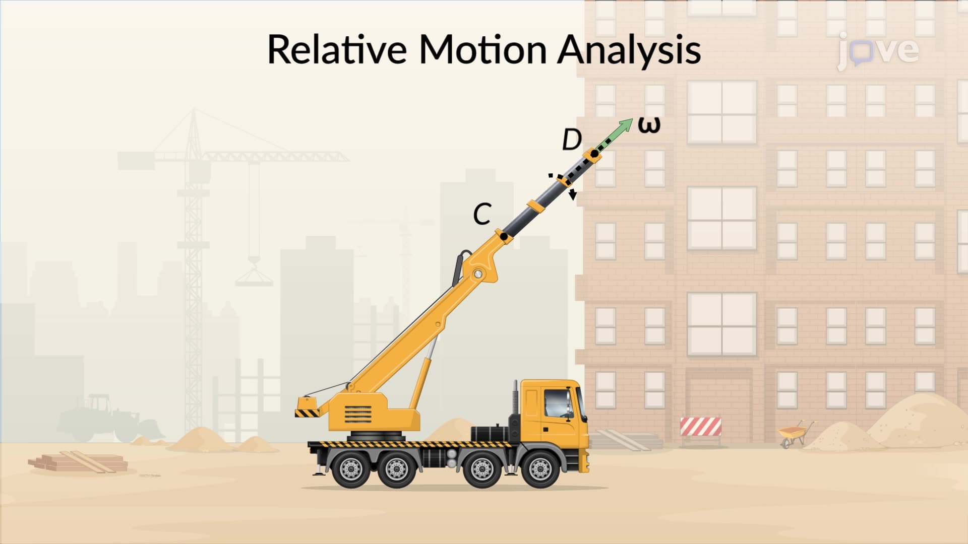
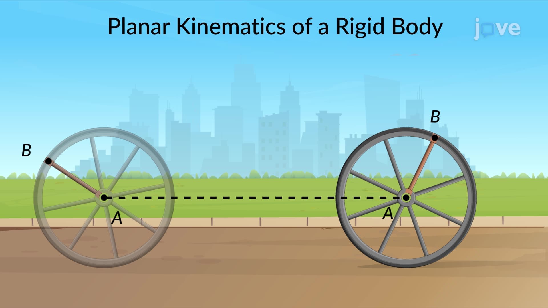
The beauty of this analysis lies in its systematic approach to decomposing complex motion into three distinct velocity components. First, we have the absolute velocity of the reference point (like point A in our example), which represents the translation of our entire rotating coordinate system through space. Second, there's the relative velocity of our point of interest (point B) within the rotating frame itself-this is the motion you'd observe if you were sitting on the rotating frame and watching the point move. Finally, we account for the angular velocity effects, which arise because the coordinate system itself is spinning.
This three-part decomposition proves invaluable in AP Physics C: Mechanics courses and college-level dynamics classes. Students often encounter this concept when studying rigid body motion, where understanding how different points on a rotating object move becomes crucial for solving problems involving everything from car wheels rolling down inclines to industrial machinery components.
Real-World Engineering Applications
Consider the Space Shuttle's robotic arm (Canadarm) used by NASA-engineers needed to precisely control the arm's end effector while the entire shuttle orbited Earth at 17,500 mph. The relative motion analysis using rotating axes allowed mission specialists to calculate exact positions and velocities despite the complex combination of orbital motion, shuttle attitude changes, and arm movement. Similarly, wind turbine designers at General Electric use these principles to analyze blade stress and fatigue, accounting for both the blade rotation and the nacelle's yaw movement as it tracks wind direction.
Mastering the Concept for Academic Success
For students preparing for standardized tests like the AP Physics C exam or college engineering assessments, this topic frequently appears in problems involving pulleys, gears, and linkages. The key insight is recognizing when to set up a rotating coordinate system-typically when you have a clear axis of rotation and want to simplify the relative motion of other components. Practice problems often involve scenarios like analyzing the motion of a point on a rolling wheel or determining velocities in planetary gear systems used in automotive transmissions.
Frequently Asked Questions
Relative motion analysis using rotating axes is a method for analyzing complex motion by establishing a coordinate system that both translates and rotates with part of the system. Use it when dealing with mechanical systems involving simultaneous rotation and translation, such as robotic arms, aircraft landing gear, or any situation where a point moves relative to a rotating reference frame.
AP Physics C frequently tests this concept through problems involving rolling objects, pulley systems, and rigid body rotation. You'll typically need to identify velocity components, apply vector addition principles, and solve for unknown velocities or accelerations. The exam often combines this with energy conservation or Newton's laws for comprehensive problem-solving.
Students often forget to include the angular velocity contribution to the total velocity, focusing only on the relative motion within the rotating frame. Remember that the absolute velocity always includes three terms: the reference point velocity, relative velocity in the rotating frame, and the cross product of angular velocity with position vector.
Aerospace engineers use relative motion analysis for everything from aircraft control surface design to spacecraft docking procedures. For example, when the SpaceX Dragon capsule approaches the International Space Station, engineers must account for the station's orbital motion, its rotation, and the capsule's approach trajectory-all requiring sophisticated relative motion calculations with rotating reference frames.
While vector calculus provides deeper insight, you can grasp the fundamental concepts with solid algebra and basic trigonometry skills. High school students in AP Physics C successfully learn this topic using vector addition and component analysis. The mathematical complexity increases in advanced engineering courses, but the core principles remain accessible.
Start by drawing clear diagrams showing both the fixed and rotating coordinate systems, then systematically identify each velocity component before combining them. Practice with problems involving familiar objects like wheels, pulleys, and simple linkages before tackling more complex scenarios. Focus on understanding when and why to choose rotating axes over fixed reference frames.
Consider studying Coriolis and centrifugal effects, three-dimensional rigid body dynamics, or gyroscopic motion. These topics build directly on relative motion analysis and appear in advanced physics courses, aerospace engineering programs, and mechanical engineering dynamics classes at universities like MIT and Stanford.
Related Micro-courses

10 Concepts

8 Concepts

20 Concepts