Loading concepts…


13 Concepts
10 Concepts
17 Concepts
6 Concepts
20 Concepts
9 Concepts
17 Concepts
14 Concepts
19 Concepts
13 Concepts
12 Concepts
12 Concepts
4 Concepts
5 Concepts
12 Concepts
13 Concepts
10 Concepts
8 Concepts
20 Concepts
12 Concepts
18 Concepts
4 Concepts
6 Concepts
10 Concepts
4 Concepts
9 Concepts
7 Concepts
8 Concepts
 8 Concepts
 5.8K Views
 Popular topics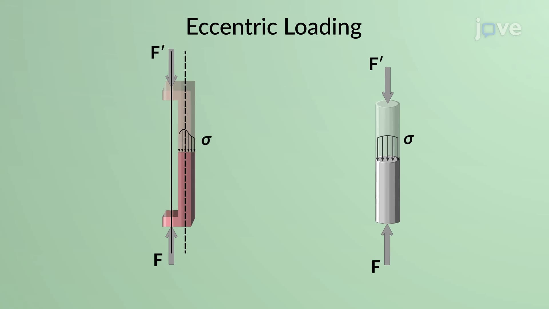

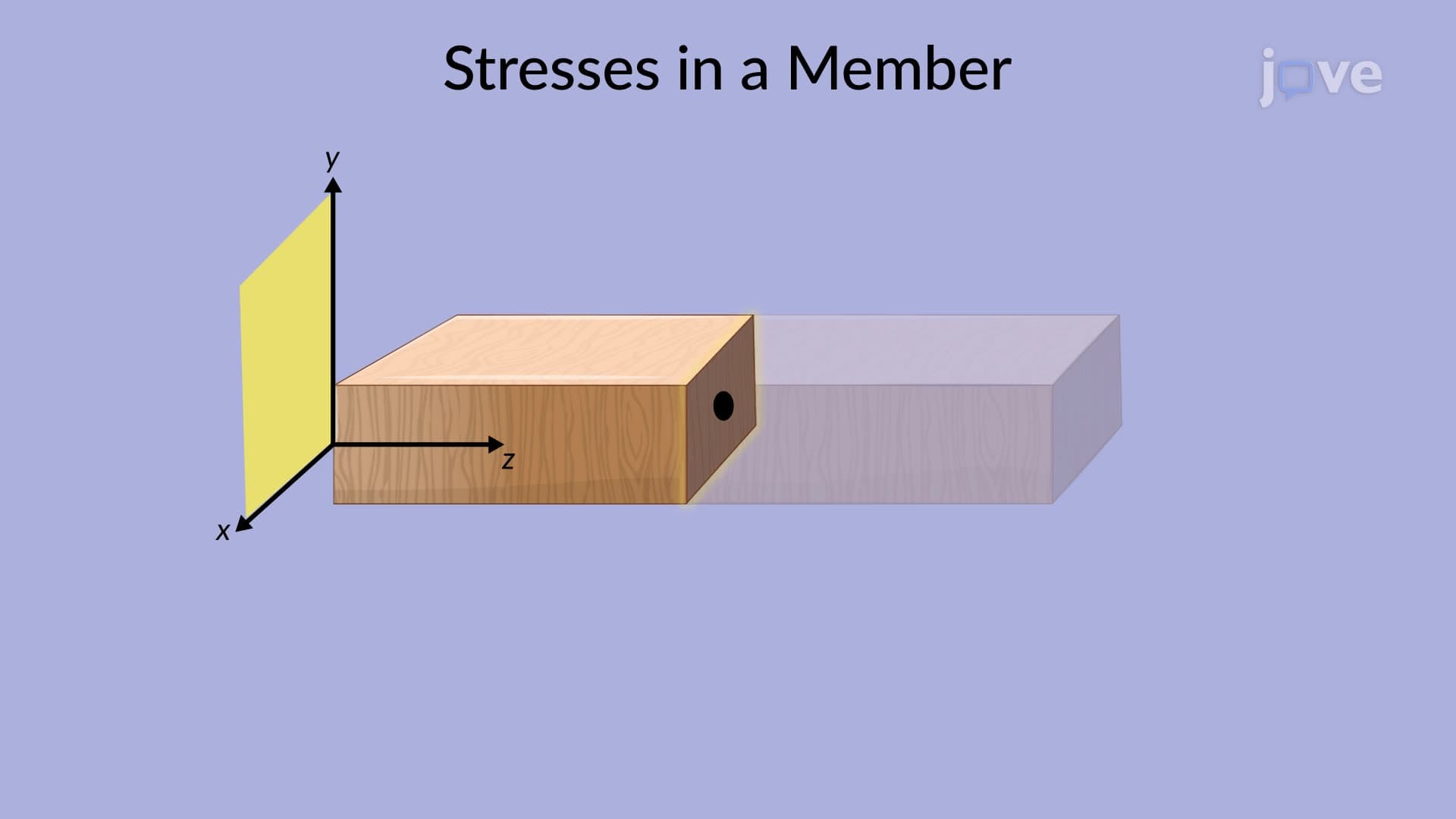
The concept of stress forms the foundation of mechanics of materials, defining how forces distribute within deformable bodies under various loading conditions. This JoVE Coach micro-course explores normal stress, shearing stress, and bearing stress through practical applications like bridge trusses, bolted connections, and structural joints. Students examine stress on oblique planes, multi-axial loading conditions, and design considerations including allowable stress and factor of safety calculations essential for safe structural engineering.
1. Normal Stress Fundamentals: Normal stress develops when axial forces create internal resistance perpendicular to cross-sectional areas. In bridge truss members and structural columns, this stress equals force divided by cross-sectional area (σ = F/A). Uniform stress distribution occurs only under centric loading through the section centroid. Eccentric loading creates non-uniform stress patterns due to additional bending moments. Understanding stress in deformable bodies requires recognizing that calculated values represent average stresses across sections rather than point-specific values.
2. Shearing Stress Analysis: Shearing stress occurs when transverse forces create internal resistance parallel to cross-sectional planes. Bolted connections in steel structures experience single or double shear depending on joint configuration. Unlike uniform normal stress assumptions, shearing stress varies from zero at member surfaces to maximum values exceeding average calculations. Double shear connections distribute forces across two planes, reducing average stress by half compared to single shear arrangements.
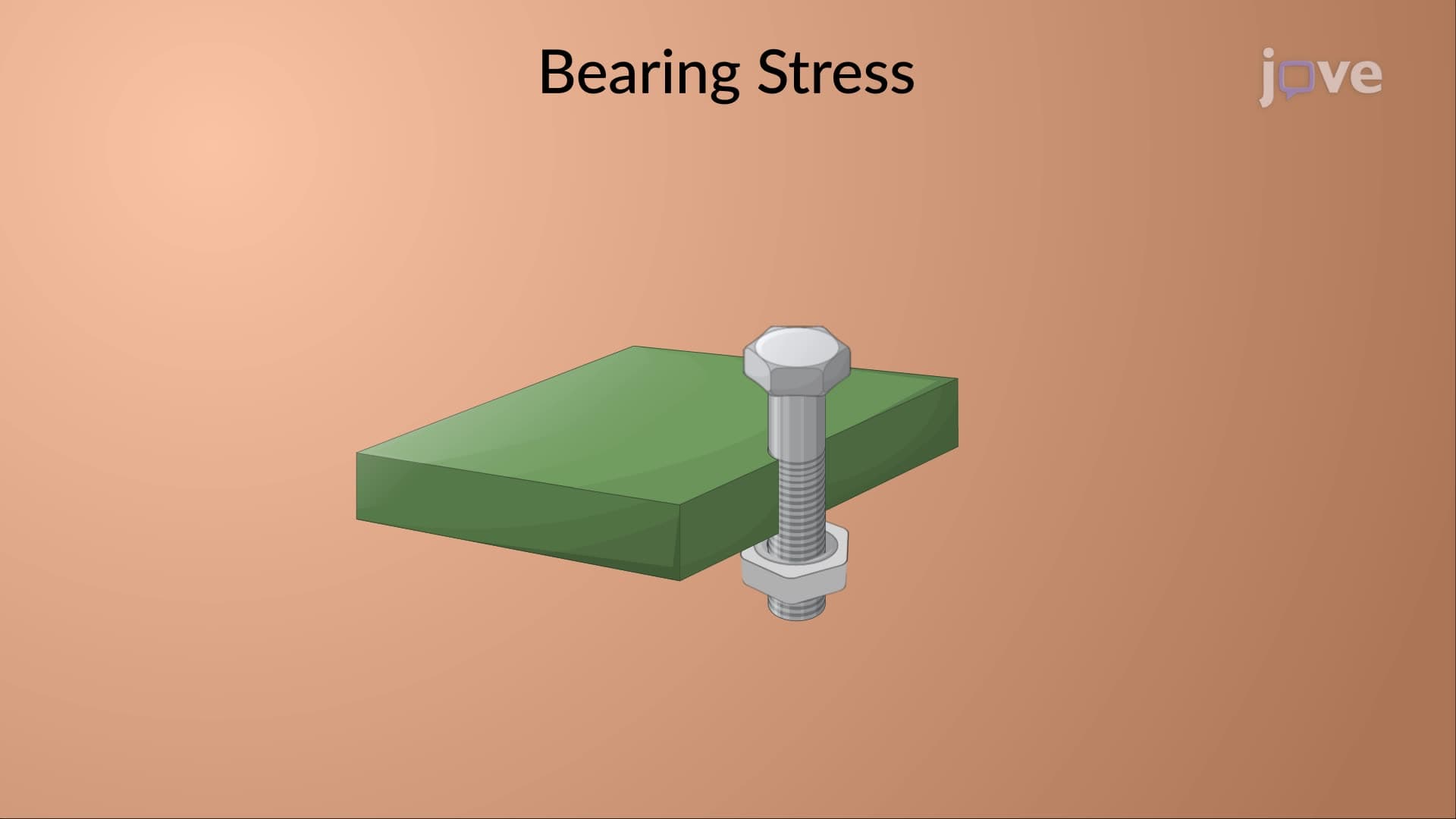
3. Bearing Stress in Connections: Bearing stress results from contact pressure between connected structural elements, commonly occurring in bolted and pinned joints. This localized stress concentrates where bolt surfaces contact plate materials, calculated as bearing force divided by projected contact area (bolt diameter times plate thickness). Understanding bearing stress prevents connection failures in steel framework buildings and mechanical assemblies where concentrated loads transfer between components.
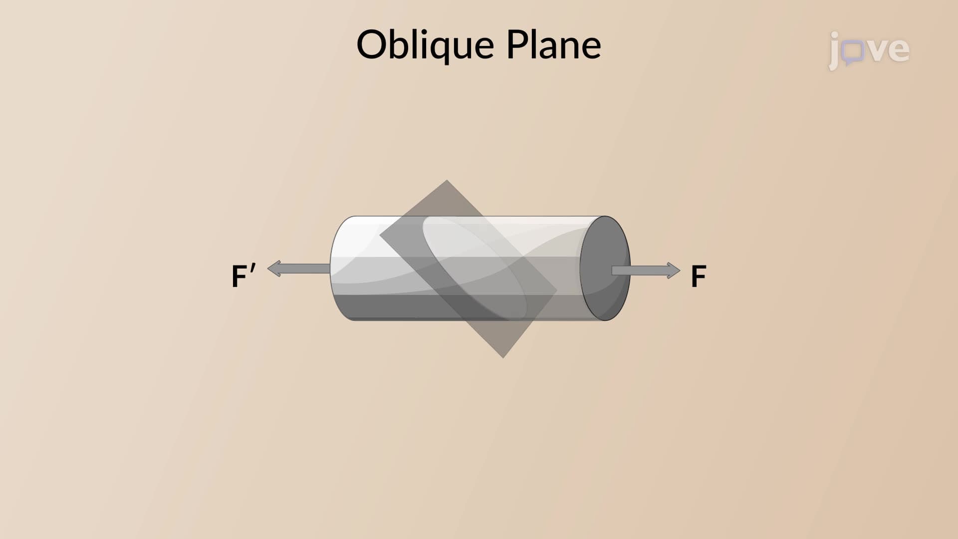
4. Stress on Oblique Planes: Oblique plane analysis reveals how stress components vary with sectional plane orientation. Normal stress reaches maximum values when sections align perpendicular to loading directions and approaches zero for parallel orientations. Shearing stress maximizes at 45-degree angles and becomes zero for parallel or perpendicular planes. This principle explains failure patterns in materials like concrete beams and timber members under various loading conditions.
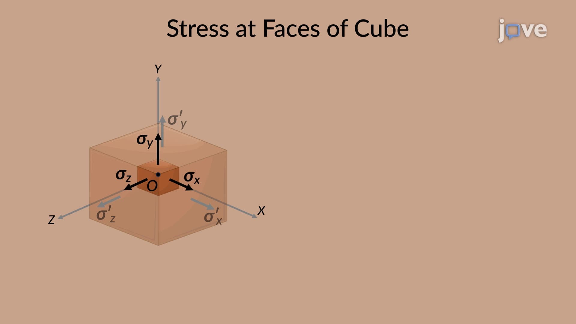
5. Multi-Axial Stress States: Complex loading creates three-dimensional stress conditions requiring analysis of normal and shearing stress components on multiple planes. Six independent stress components (three normal, three shearing) define complete stress states at any point. Equilibrium requirements establish relationships between shearing stress components, demonstrating that shearing stresses occur in perpendicular pairs. This analysis applies to pressure vessels, machine components, and structural members under combined loading.
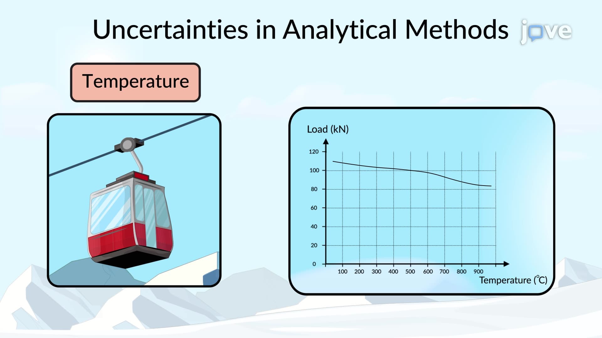
6. Design Safety Considerations: Ultimate strength testing determines material failure limits under increasing loads until fracture occurs. Factor of safety represents the ratio between ultimate and allowable loads, providing reserve capacity for safe operation. Selection considers material property variations, loading uncertainties, failure consequences, and structural importance. Modern Load and Resistance Factor Design (LRFD) methods separate structural and loading uncertainties, distinguishing between dead loads (permanent) and live loads (temporary) for more precise safety assessments.