13 Concepts
10 Concepts
17 Concepts
6 Concepts
20 Concepts
9 Concepts
17 Concepts
14 Concepts
19 Concepts
13 Concepts
12 Concepts
12 Concepts
4 Concepts
5 Concepts
12 Concepts
13 Concepts
10 Concepts
8 Concepts
20 Concepts
12 Concepts
18 Concepts
4 Concepts
6 Concepts
10 Concepts
4 Concepts
9 Concepts
7 Concepts
8 Concepts
Torsion mechanics governs how shafts twist under applied torques, from automotive drive shafts to industrial machinery. This comprehensive course covers torsional shear stress in circular and non-circular shafts, analyzing stress distributions, deformation patterns, and failure mechanisms. Students master the torsion formula, polar moment calculations, and angle of twist computations essential for mechanical engineering applications. JoVE Coach guides learners through practical shaft design principles used in American manufacturing and aerospace industries.
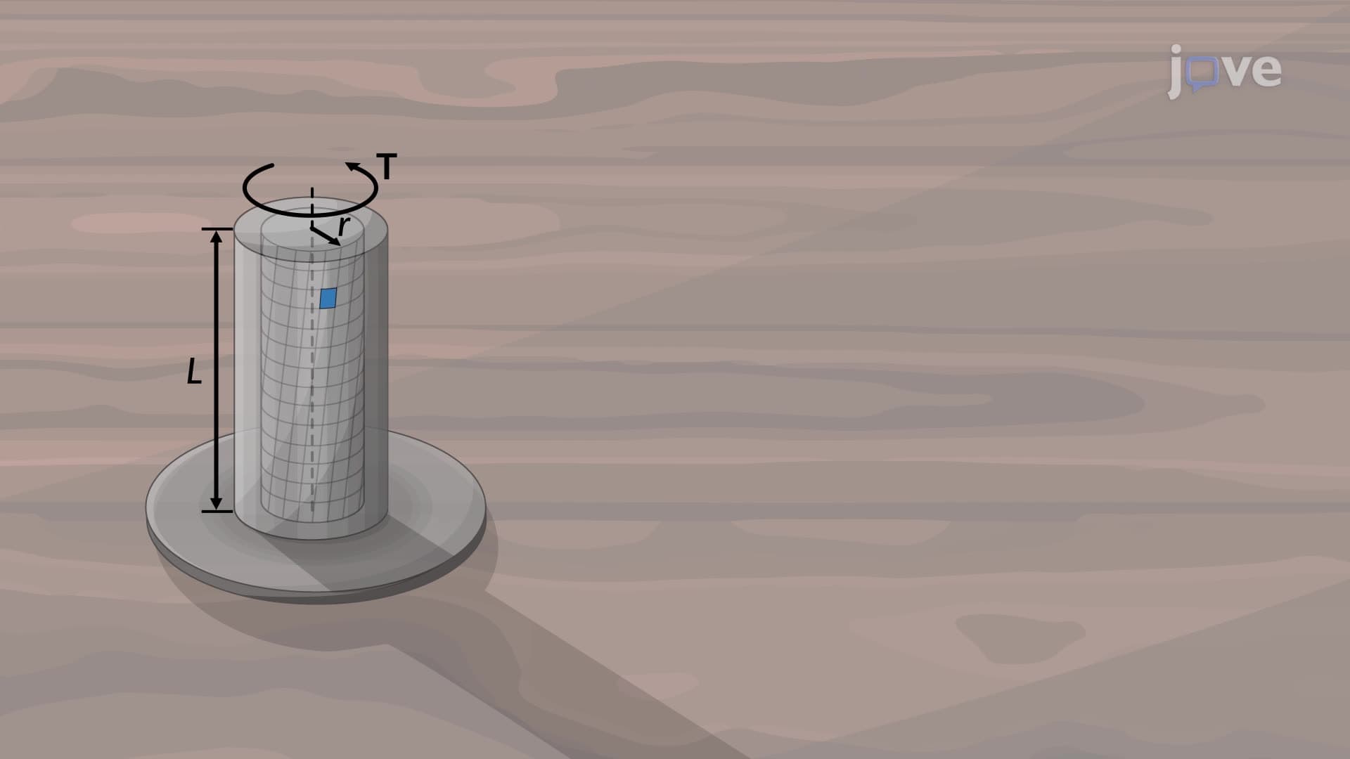
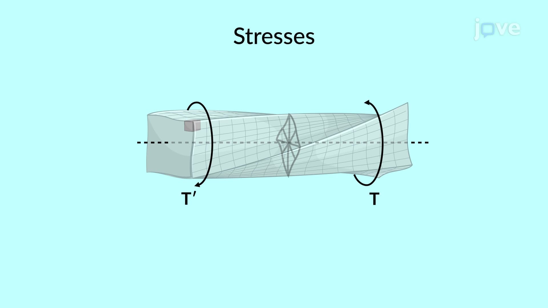
1. Fundamental Torsion Theory and Equilibrium Analysis Torsion occurs when shafts experience twisting moments, creating internal shearing forces that maintain equilibrium. The relationship between applied torque and internal shear forces forms the foundation for all torsional analysis. Understanding free-body diagrams and equilibrium equations helps students visualize how torques distribute throughout shaft cross-sections, essential for analyzing everything from car axles to helicopter drive shafts used in American aerospace applications.
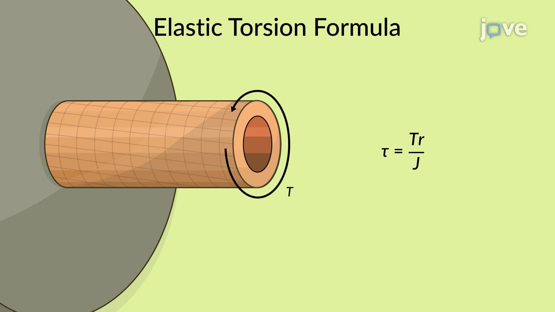
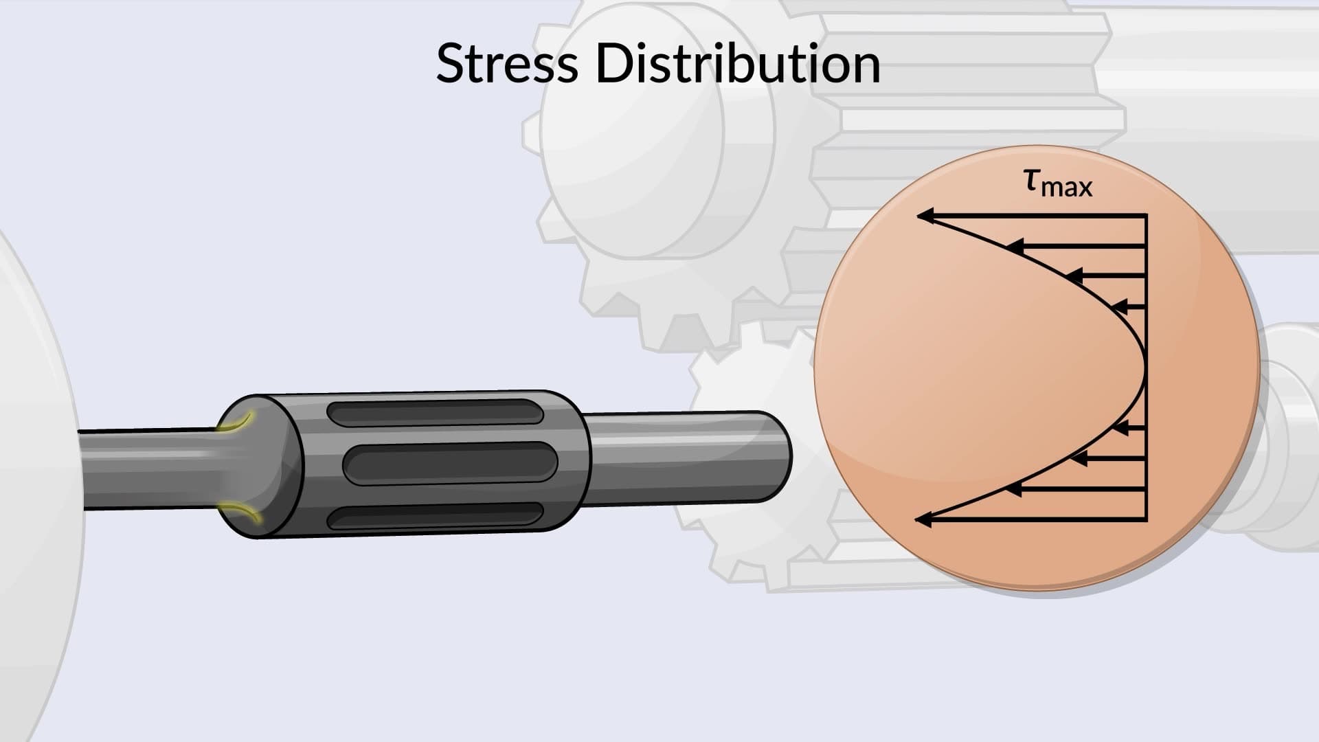
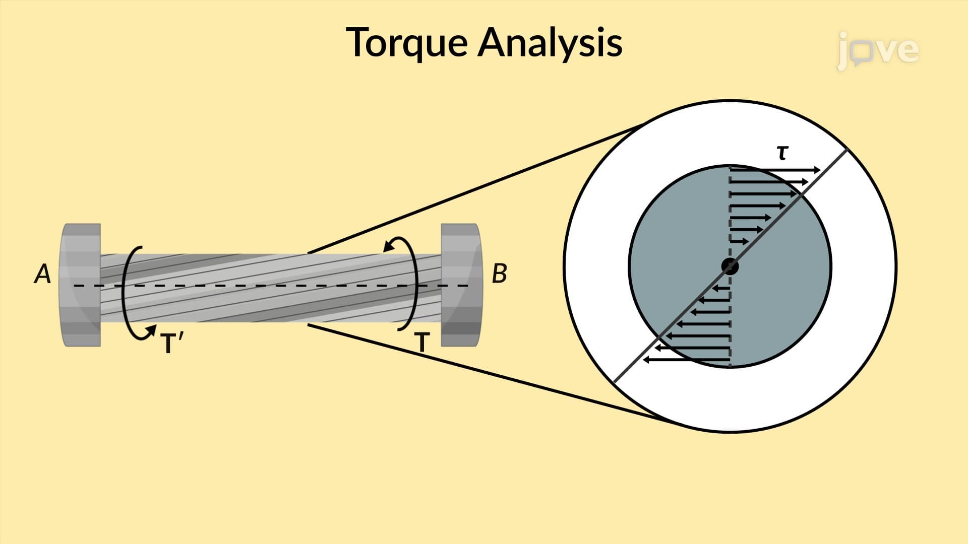
2. Torsional Shear Stress Distribution in Circular Shafts In circular shafts, shear stress varies linearly from zero at the center to maximum at the outer surface. This unique stress distribution occurs because circular cross-sections remain plane during twisting. The torsion formula τ = Tr/J relates shear stress to applied torque, radial distance, and polar moment of inertia. This principle applies to designing transmission shafts in American automotive manufacturing and turbine shafts in power generation facilities.
3. Polar Moment of Inertia and Cross-Sectional Properties The polar moment of inertia (J) measures a cross-section's resistance to torsion, calculated as J = πd⁴/32 for solid circular shafts and J = π(D⁴-d⁴)/32 for hollow shafts. Hollow shafts provide excellent strength-to-weight ratios, making them ideal for aircraft applications. Understanding these geometric properties enables engineers to optimize shaft designs for specific torque requirements while minimizing weight and material costs in American manufacturing industries.
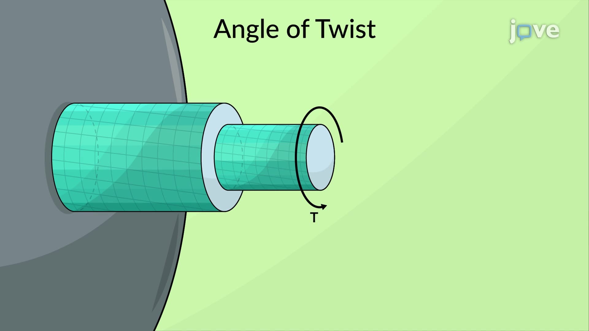
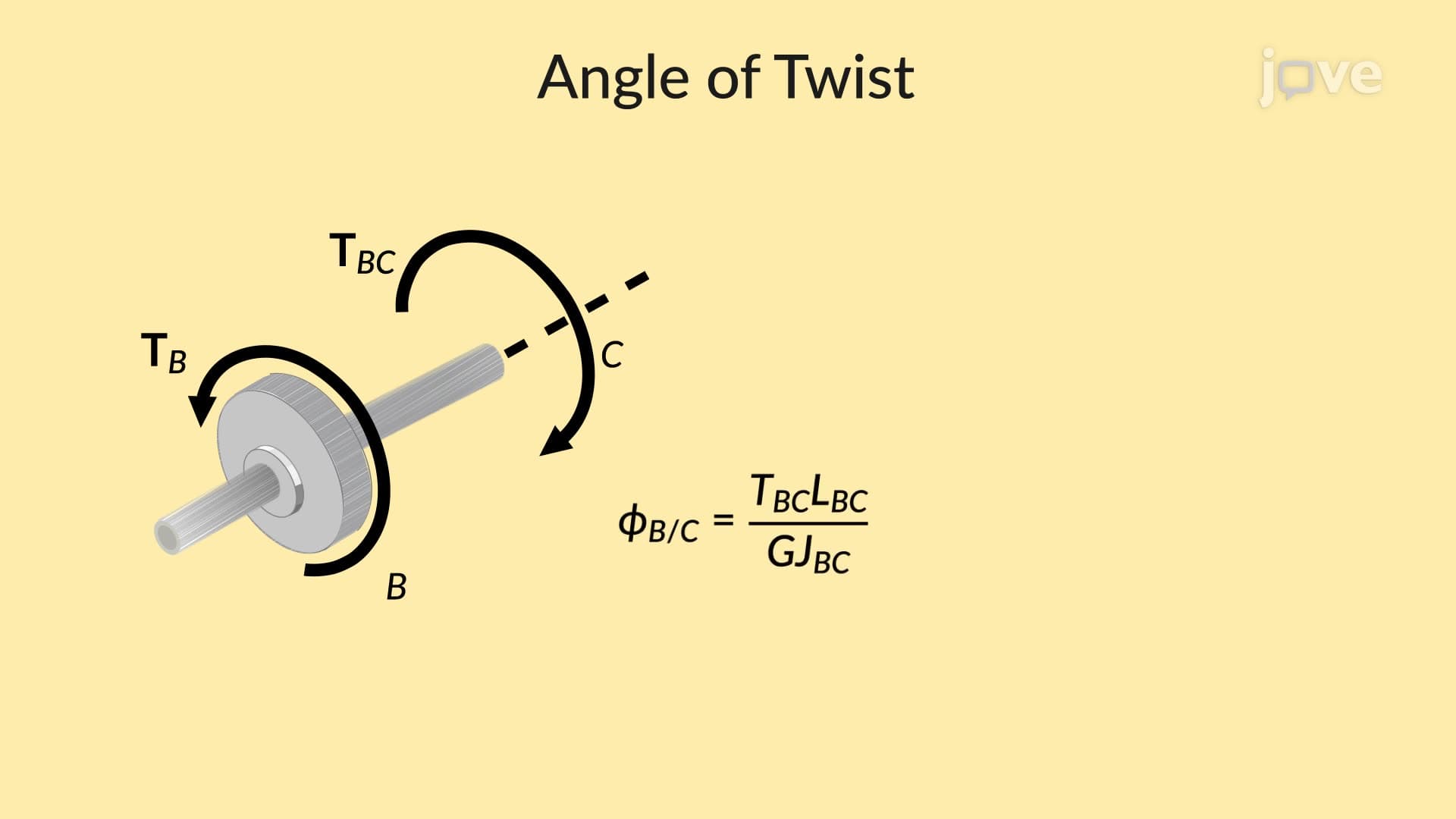
4. Angle of Twist Calculations and Deformation Analysis The angle of twist φ = TL/(GJ) quantifies shaft rotation under torsional loading, where G represents the material's modulus of rigidity. This calculation proves crucial for determining shaft stiffness in precision applications like machine tools and robotics. Multiple torque applications require superposition principles, while varying cross-sections need integration techniques commonly used in analyzing complex drive systems found in American manufacturing equipment and aerospace propulsion systems.
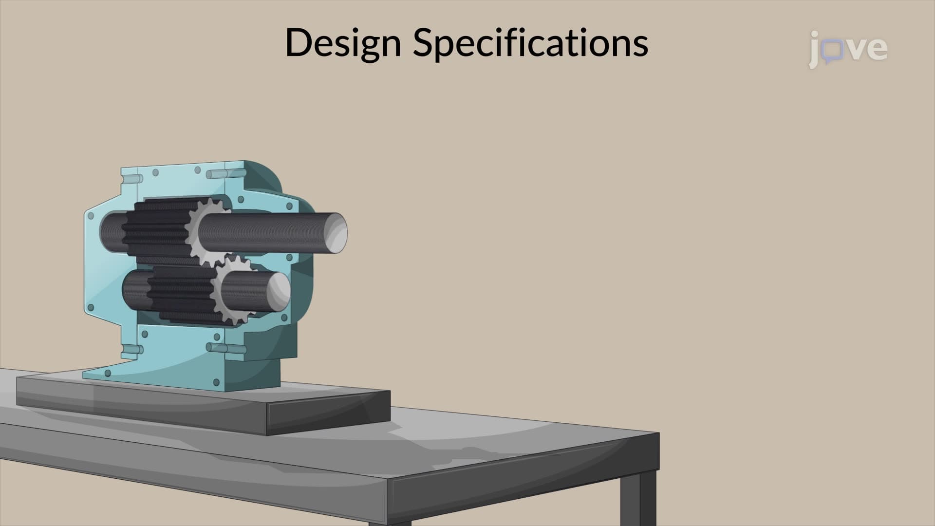
5. Shaft Design for Power Transmission Applications Power transmission shaft design begins with the relationship P = Tω, connecting power requirements to torque and rotational speed. Engineers select appropriate materials and dimensions ensuring maximum shear stress remains below allowable limits. Design considerations include fatigue resistance, critical speeds, and manufacturing tolerances. These principles apply directly to designing drivetrain components for American automotive, agricultural, and industrial machinery where reliability and efficiency remain paramount concerns.
6. Stress Concentrations and Practical Design Considerations Real shafts contain keyways, shoulders, and fillets that create stress concentrations exceeding theoretical predictions. Stress concentration factors (Kt) quantify these effects, requiring designers to account for localized stress increases. Proper fillet radii and gradual diameter changes minimize stress concentrations. Understanding these factors proves essential for designing reliable shafts in American manufacturing applications where component failure could cause significant safety hazards or economic losses.
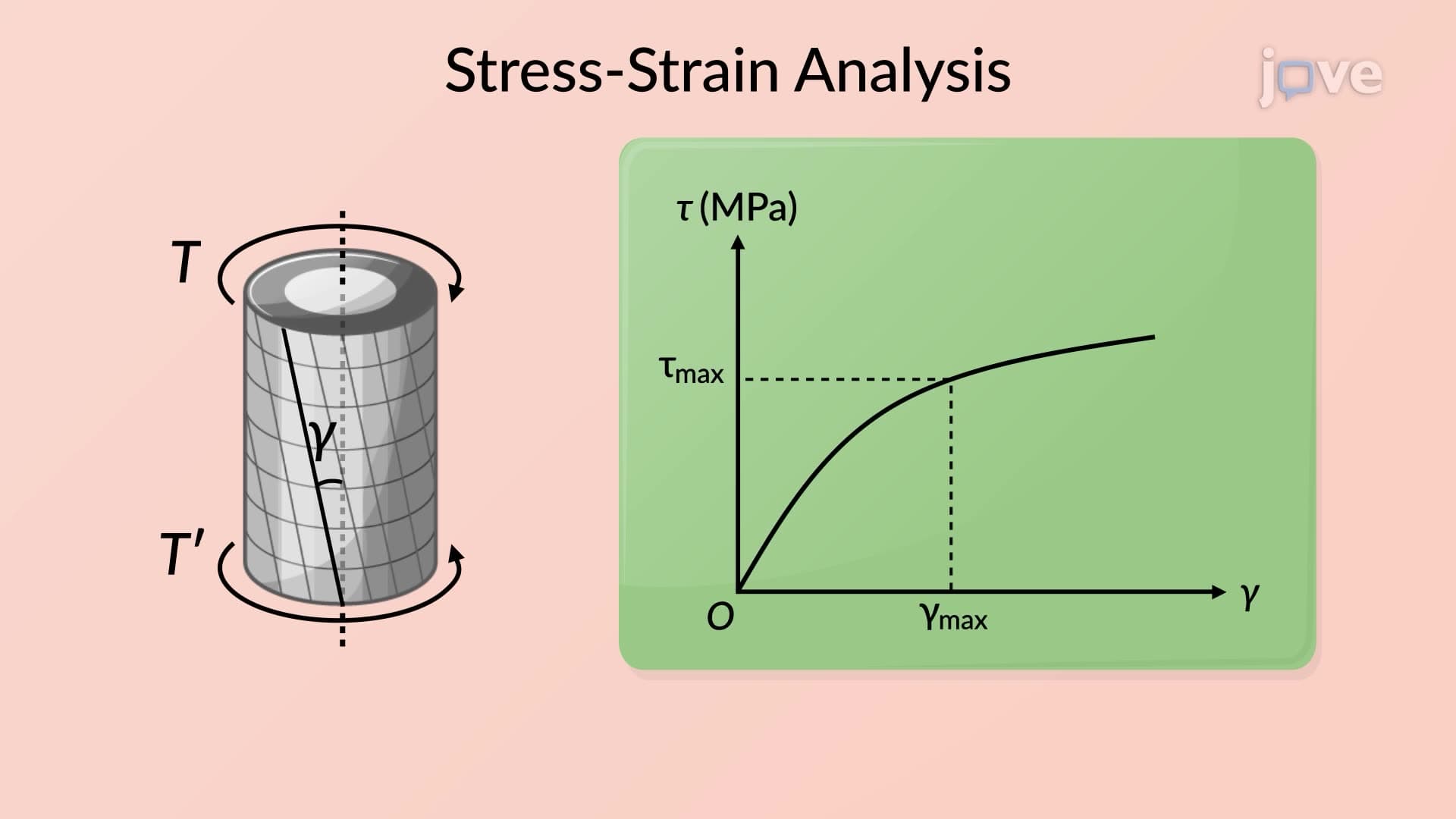
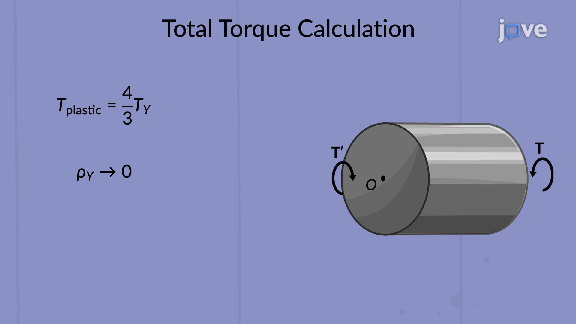
7. Plastic Deformation and Ultimate Strength Analysis When applied torques exceed material yield strength, plastic deformation occurs, permanently altering shaft geometry. The modulus of rupture represents ultimate torsional strength, while yield torque marks the onset of permanent deformation. Understanding elastoplastic behavior helps engineers design shafts with appropriate safety factors and predict failure modes. This knowledge applies to designing robust mechanical systems for American heavy industry and construction equipment applications.
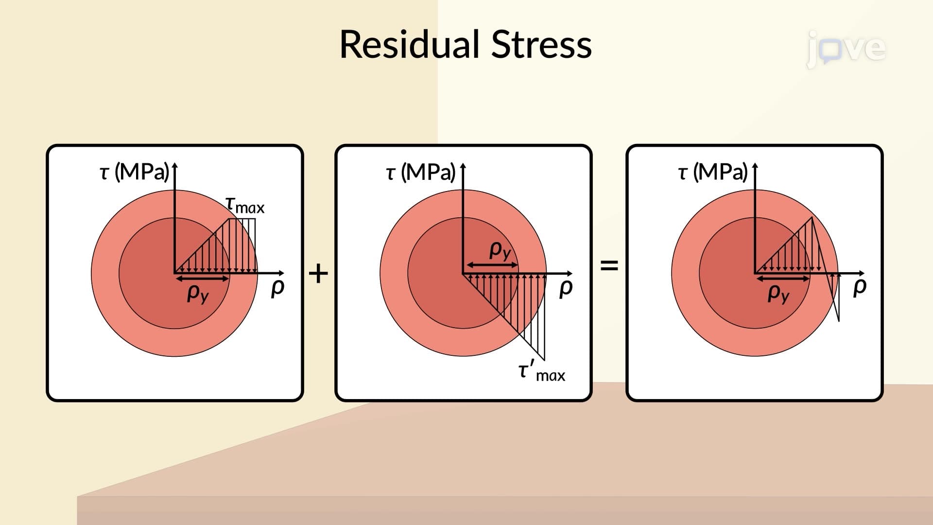
8. Residual Stresses and Loading-Unloading Cycles Plastic deformation during overloading creates residual stresses that remain after load removal. These internal stresses affect subsequent loading cycles and can either strengthen or weaken components depending on their distribution. Superposition principles help analyze residual stress patterns, crucial for understanding fatigue behavior and service life prediction in cyclically loaded shafts used in American automotive and aerospace applications where durability requirements are stringent.