Loading subject page…


5,181 views


Video Summary: What Is Design of Transmission Shafts
Ever wondered how a Formula 1 race car's engine power reaches its wheels at 15,000 RPM without the shaft snapping? The design of transmission shafts is the critical engineering process that ensures power transfer components can handle extreme torque and rotational speeds safely. From NASCAR vehicles to industrial manufacturing equipment across the United States, transmission shaft design prevents catastrophic mechanical failures by calculating precise material specifications and dimensional requirements. Engineers must balance power transmission efficiency with structural integrity, considering factors like maximum shearing stress and elastic limits. Watch the full video on JoVE Coach to master this concept with expert-led visuals and step-by-step explanations.
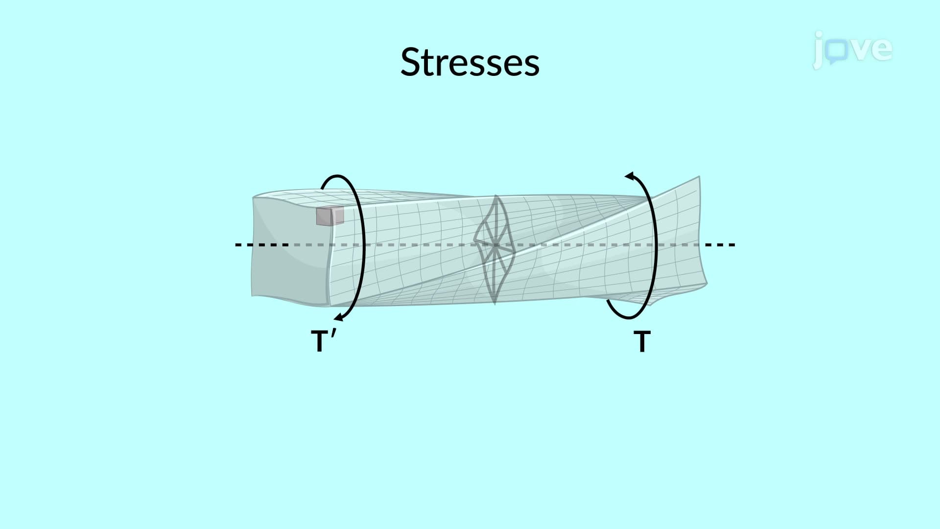
The design of transmission shafts represents a cornerstone of mechanical engineering, focusing on creating rotating components that safely transfer power between mechanical systems. This process requires engineers to balance multiple competing factors: structural integrity, material efficiency, weight considerations, and cost-effectiveness. Unlike simple static structural elements, transmission shafts must withstand complex loading conditions including torsional stress, bending moments, and dynamic forces that vary with rotational speed.
In the United States automotive industry, transmission shaft failures can lead to catastrophic accidents, making proper design calculations literally life-or-death decisions. Companies like Ford, General Motors, and Tesla invest millions in shaft design optimization, utilizing advanced computer modeling alongside fundamental engineering principles.
The foundation of transmission shaft design begins with understanding the power-torque-speed relationship: Power = Torque × Angular Velocity. This fundamental equation allows engineers to calculate the torque requirements when power output and rotational speed are specified. For example, a typical automotive transmission shaft handling 300 horsepower at 3,000 RPM must withstand approximately 525 lb-ft of torque.
This relationship becomes critical during AP Physics exams and college-level Statics courses, where students must demonstrate understanding of rotational mechanics. The ability to rearrange this equation and solve for unknown variables appears frequently on the Fundamentals of Engineering (FE) exam, which many mechanical engineering students take before graduation.
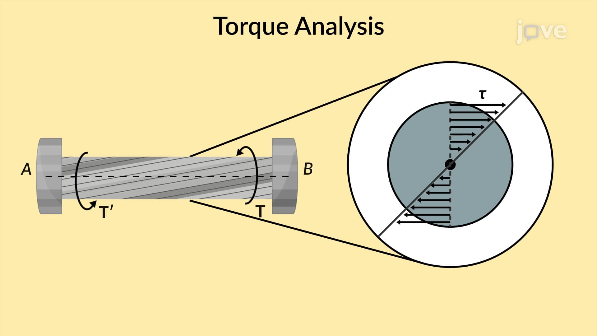
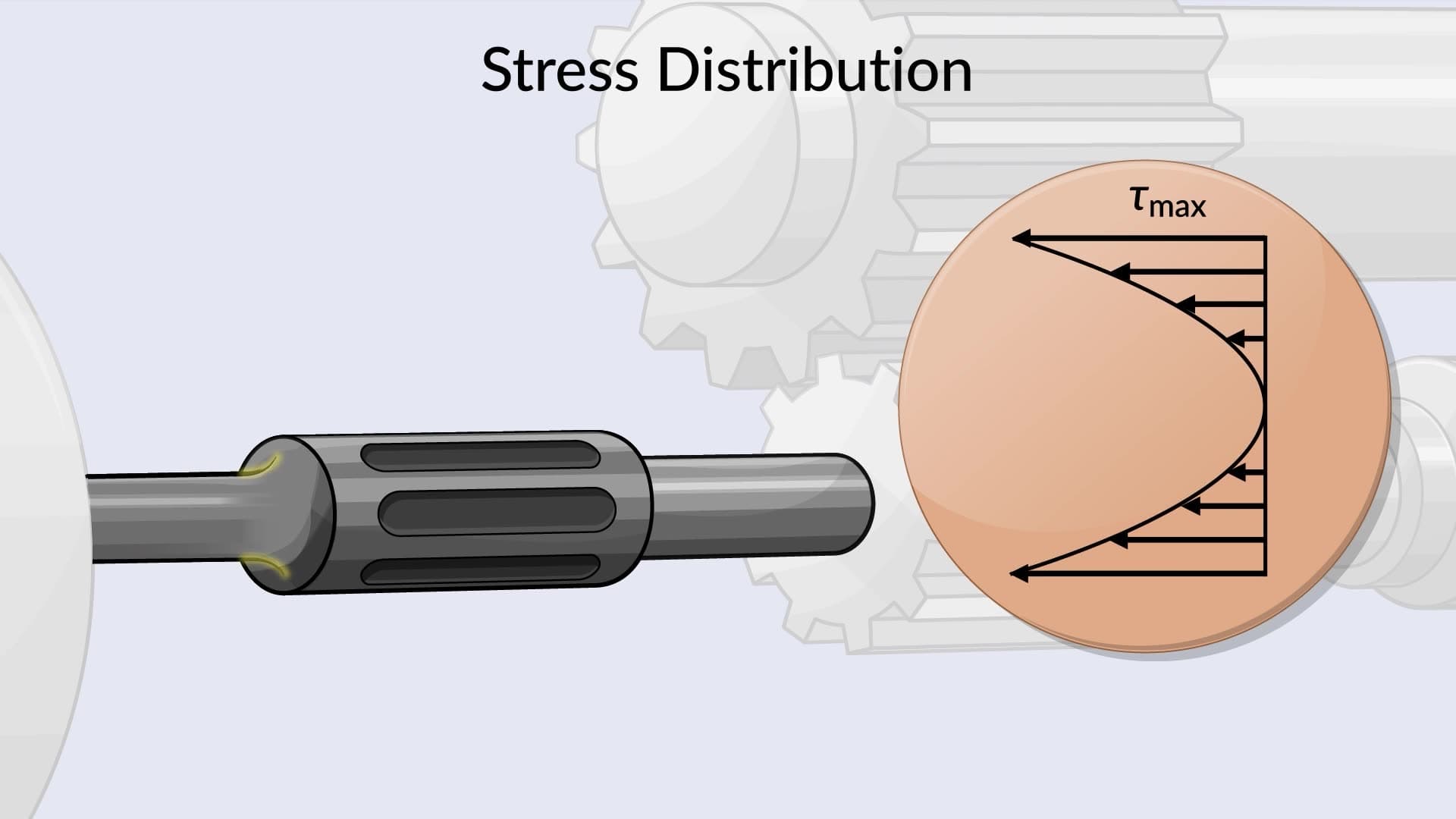
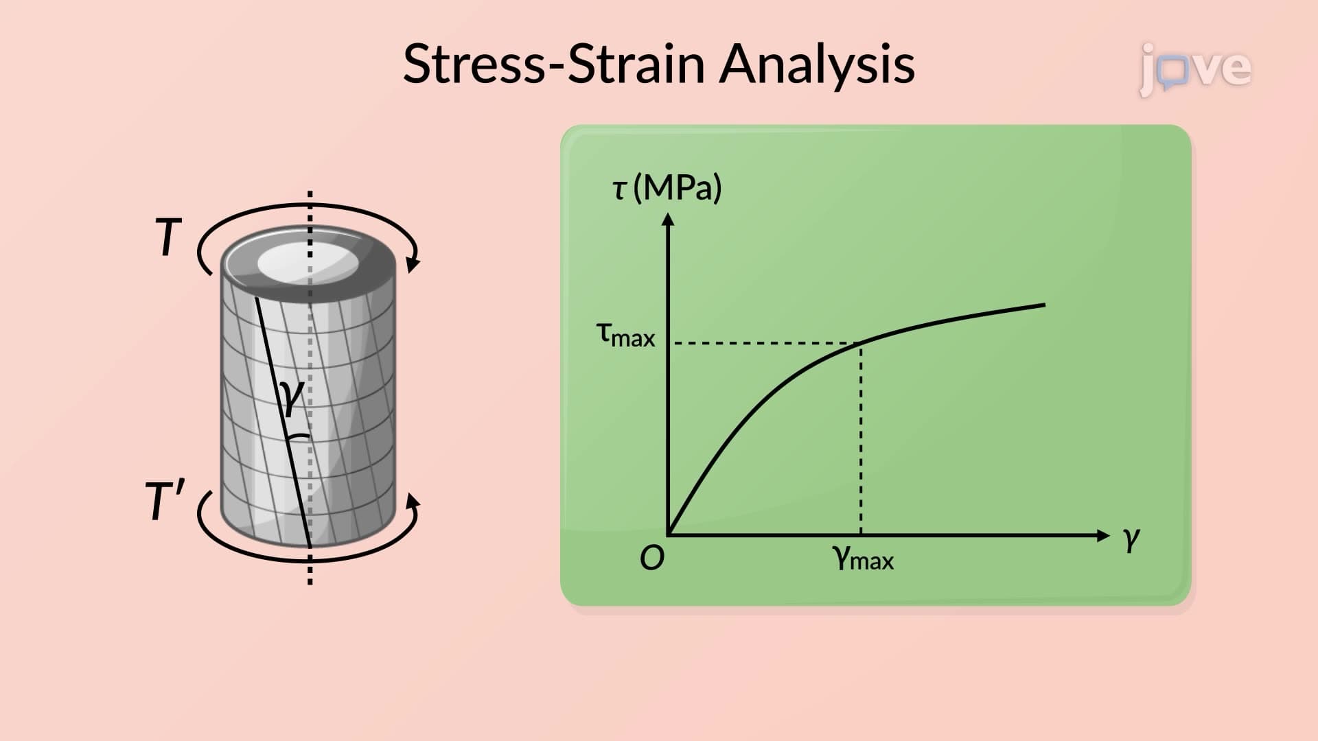
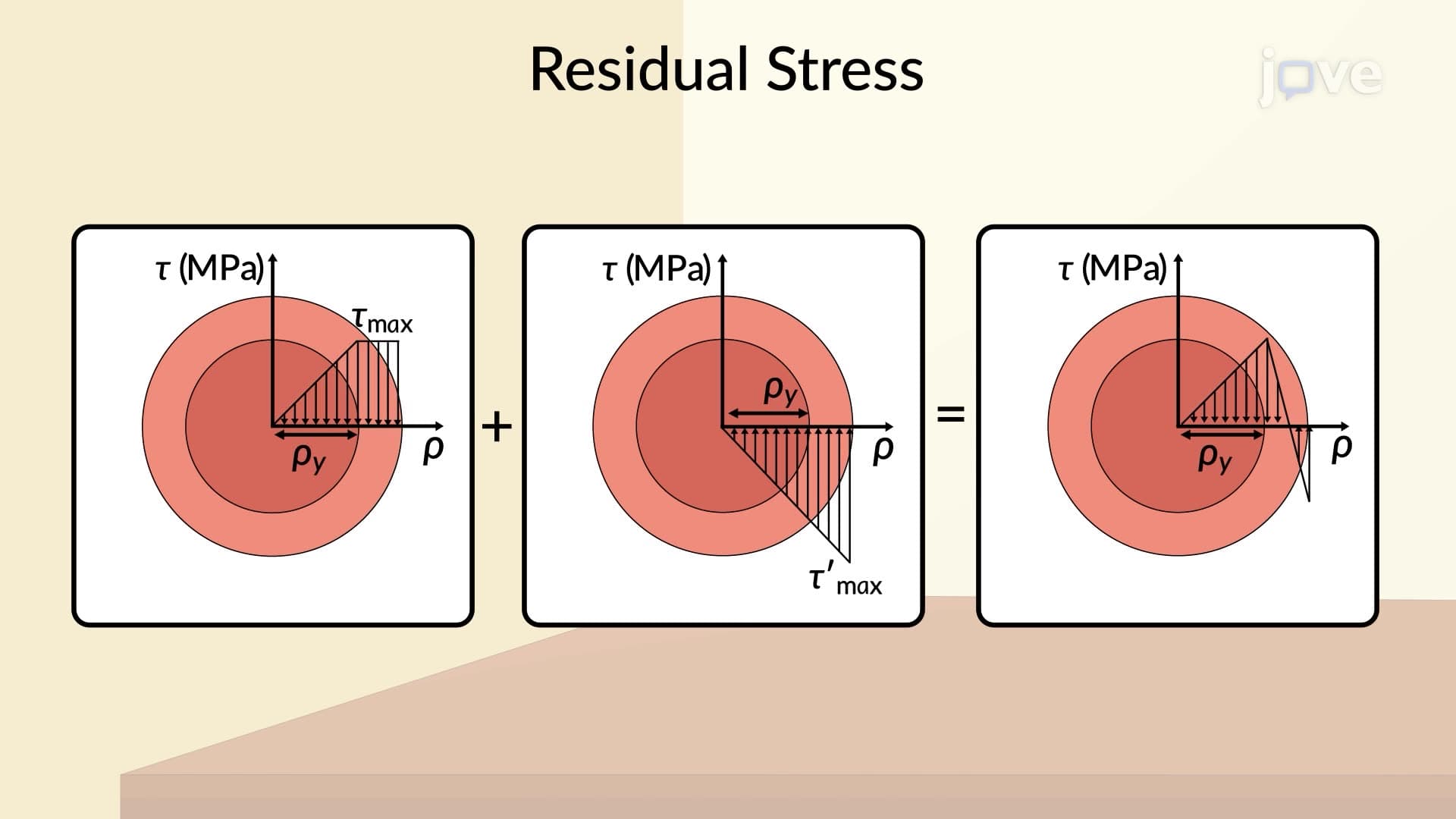
Once torque requirements are established, engineers apply the elastic torsion formula to determine minimum shaft dimensions. The maximum shearing stress must remain below the material's yield strength to prevent permanent deformation or catastrophic failure. Common materials include AISI 1040 steel for general applications and 4140 alloy steel for high-performance situations like racing transmissions.
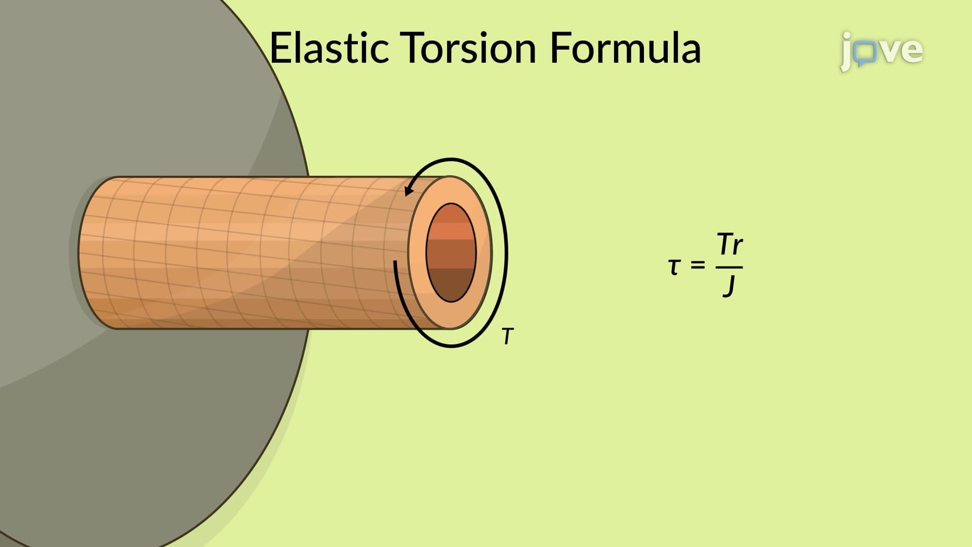
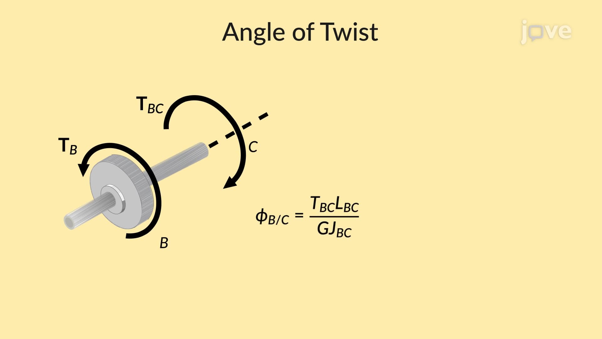
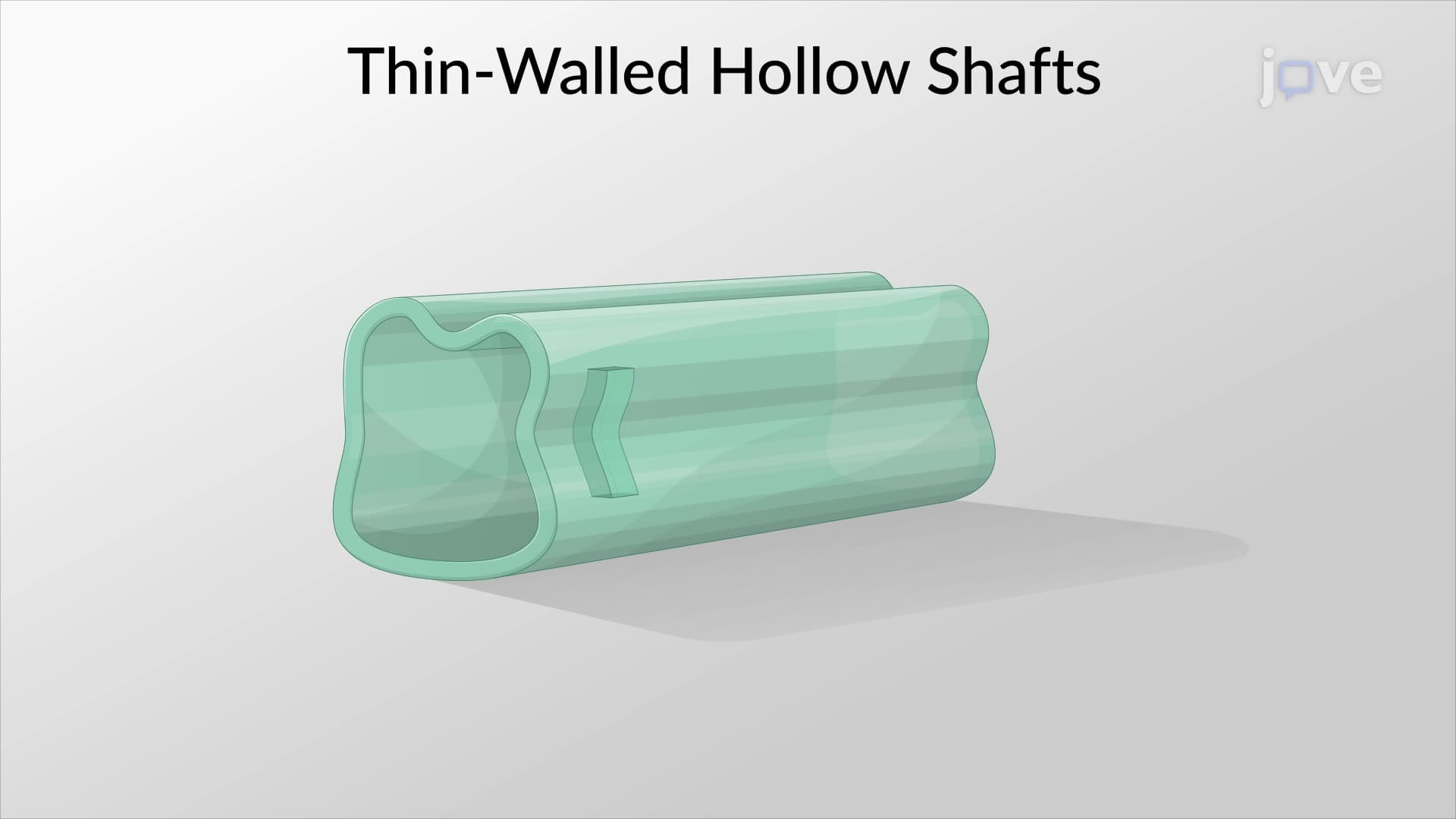
The elastic torsion formula, τ = TR/J, relates shearing stress (τ) to applied torque (T), radius (R), and polar moment of inertia (J). For solid circular shafts, J = πd⁴/32, while hollow shafts use J = π(d₄ - d₁⁴)/32. This distinction becomes crucial in aerospace applications where weight reduction drives hollow shaft selection despite increased manufacturing complexity.
Real-world transmission shaft design extends beyond basic calculations to include fatigue analysis, vibration considerations, and manufacturing constraints. Boeing's aircraft transmission systems, John Deere's agricultural equipment, and Caterpillar's heavy machinery all utilize sophisticated shaft design principles to ensure reliability under extreme operating conditions.
Modern design software like SolidWorks and ANSYS helps engineers optimize shaft geometry, but understanding fundamental principles remains essential for interpreting results and making informed design decisions.
Related Micro-courses