Loading video…


 12 Concepts
 5.2K views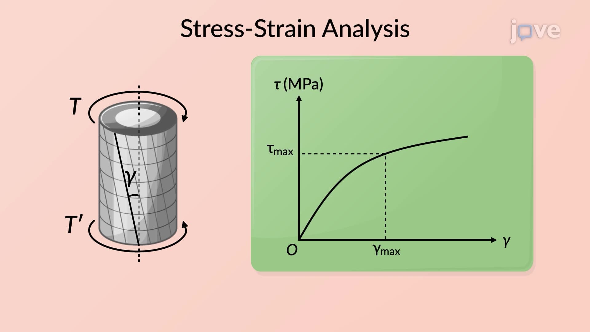

Video Summary: What Is Plastic Deformation
Ever wonder why a bent paperclip stays bent instead of springing back to its original shape? Plastic deformation occurs when materials are stressed beyond their yield strength, creating permanent changes that don't recover. Consider how aluminum aircraft components maintain their formed shapes even under extreme flight conditions-this permanent structural change is the essence of what is plastic deformation. Understanding this concept is crucial for analyzing material behavior in engineering applications, from automotive crankshafts to construction beams. Watch the full video on JoVE Coach to master this concept with expert-led visuals and step-by-step explanations.
Plastic deformation represents a fundamental shift in material behavior where applied stresses exceed the material's yield strength, resulting in permanent, irreversible changes to the object's shape or dimensions. Unlike elastic deformation, where materials return to their original form when stress is removed, plastic deformation creates lasting structural modifications that remain even after the applied forces are eliminated.
This phenomenon occurs at the molecular level when atomic bonds within the material's crystal structure are permanently displaced. The yield strength serves as the critical threshold-below this point, materials behave elastically, but beyond it, they enter the plastic region where permanent deformation begins.
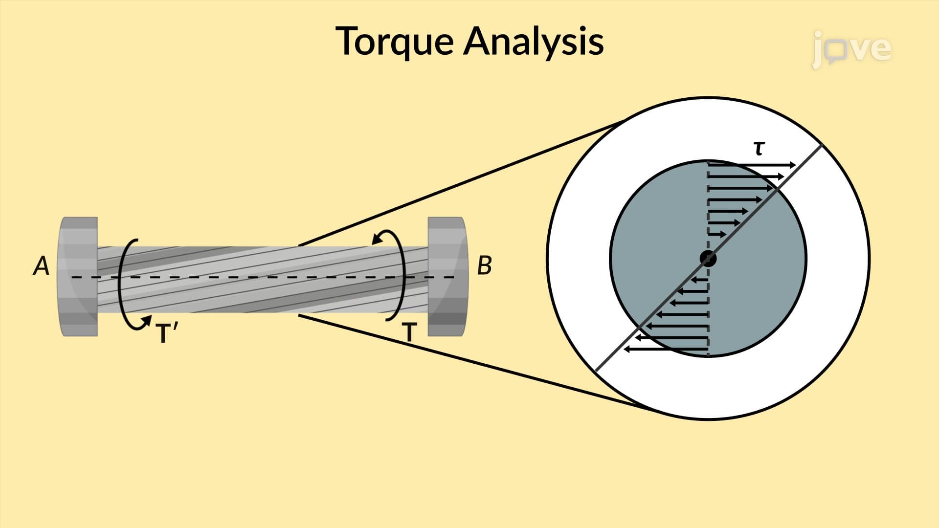
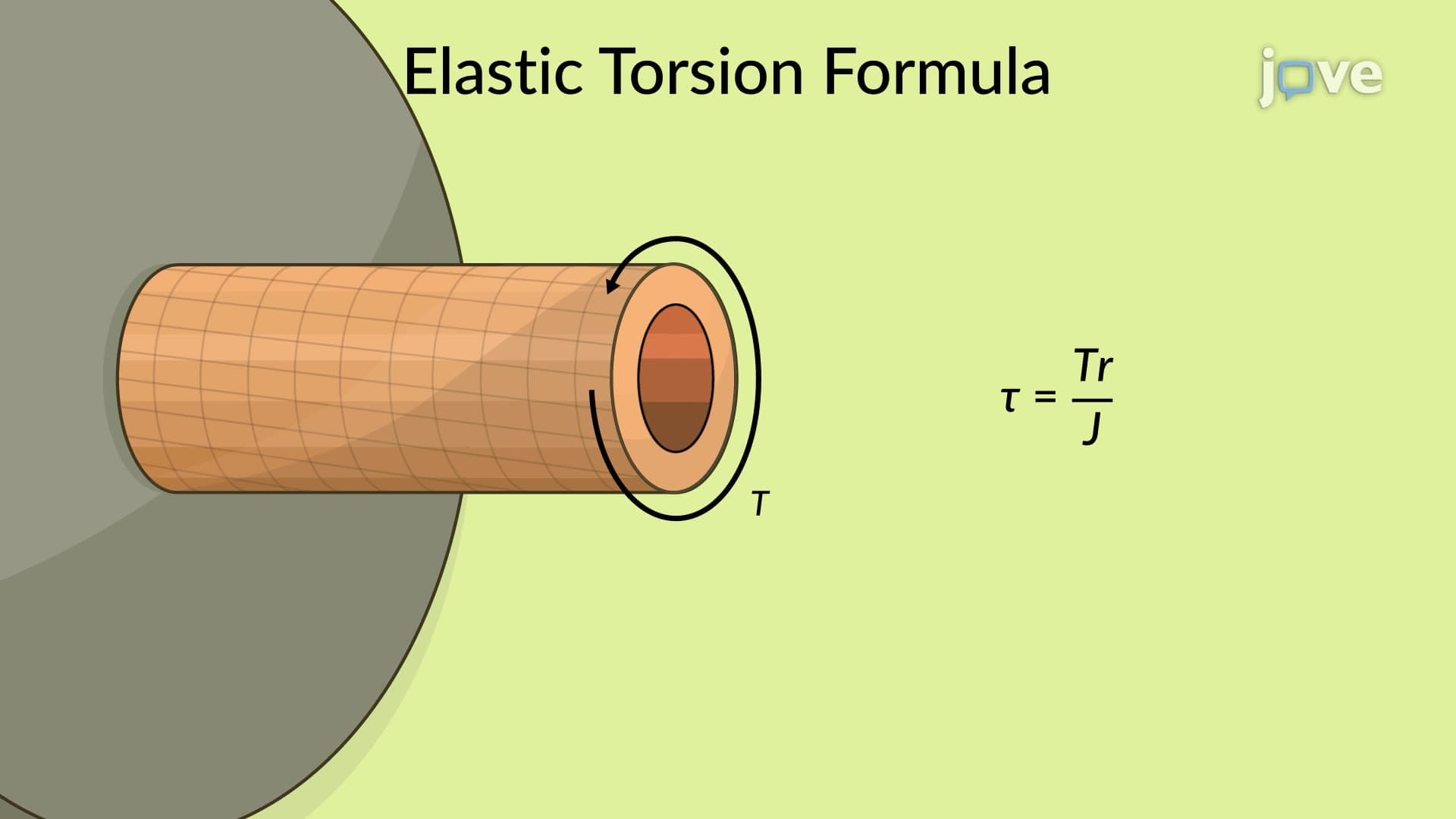
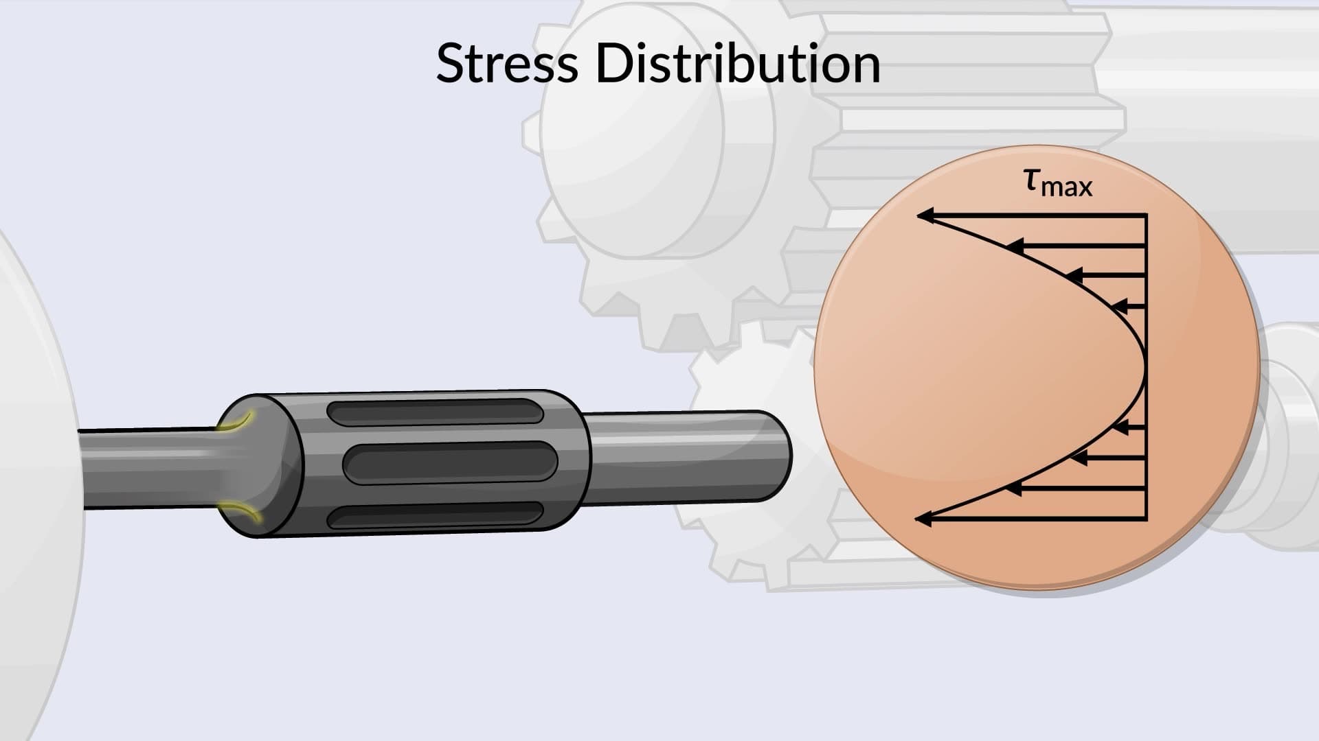
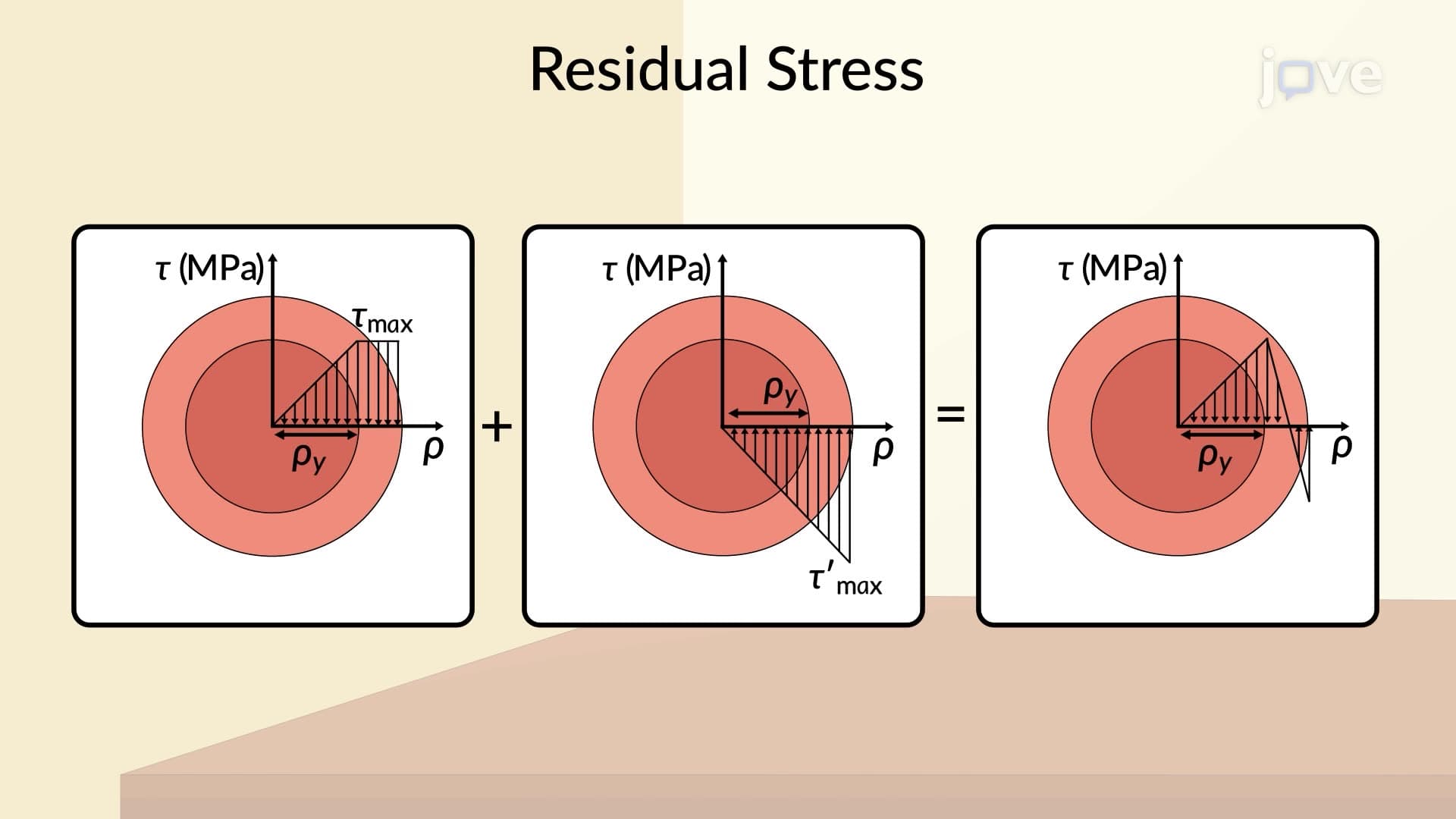
When circular shafts experience plastic deformation, the stress distribution becomes non-linear and complex. In the elastic range, shearing stress varies linearly from zero at the center to maximum at the outer surface. However, once plastic deformation begins, this relationship changes dramatically.
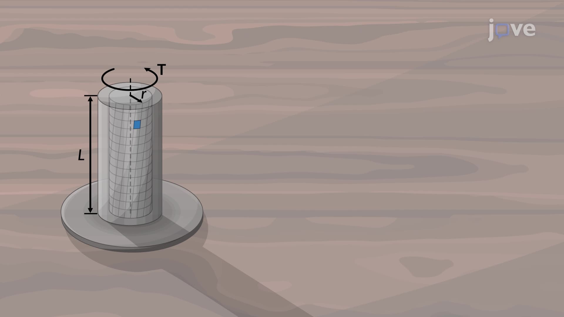
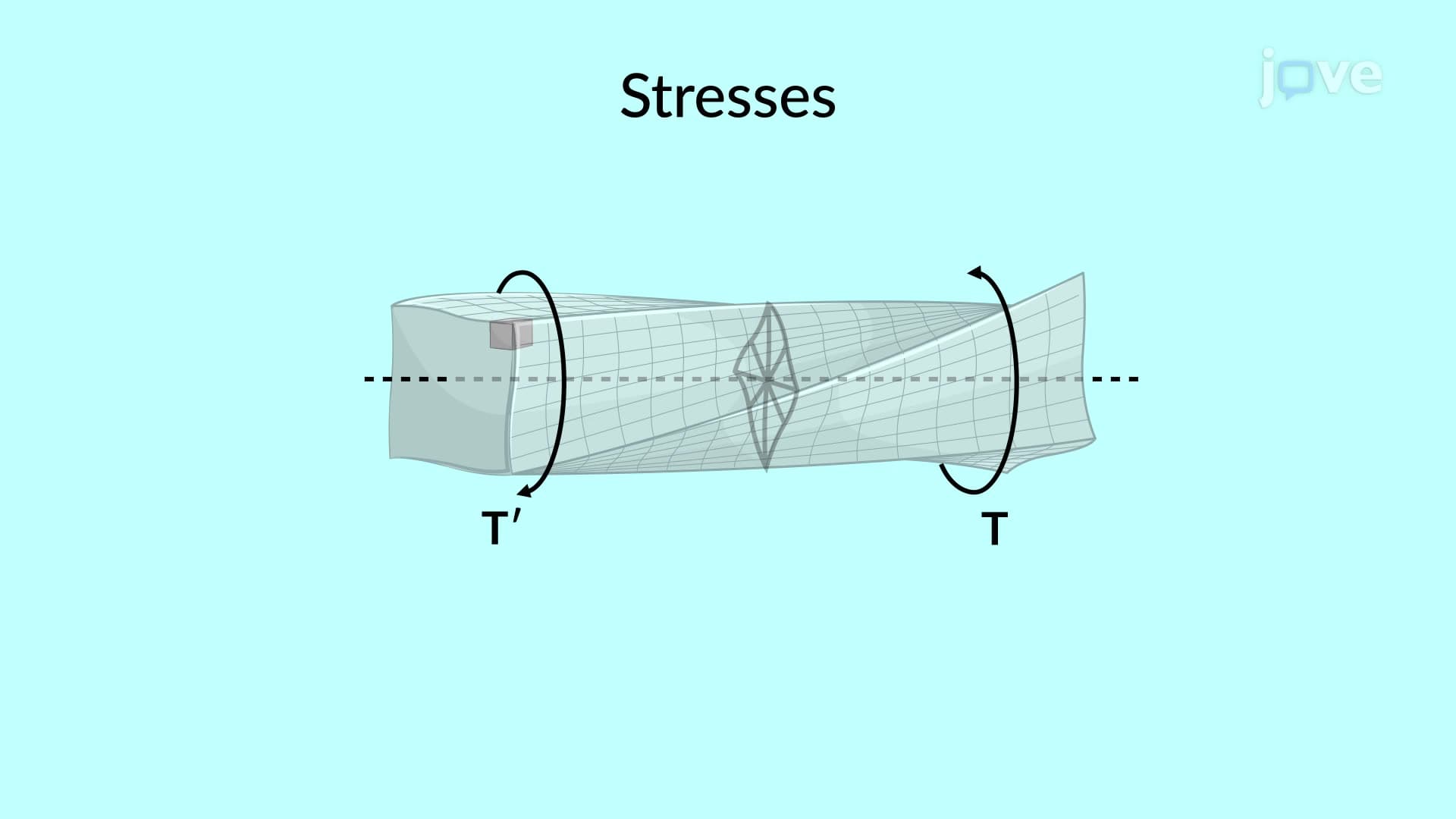
The shearing strain maintains a linear relationship with radial distance from the shaft's axis, even in the plastic range. This principle allows engineers to predict deformation patterns in rotating machinery components like drive shafts in Ford F-150 trucks or turbine rotors in General Electric power plants.
The shearing stress-strain diagram becomes crucial for understanding plastic behavior. By plotting maximum shearing stress against corresponding strain values, engineers can determine the material's plastic response characteristics. This analysis helps predict failure points and design safety margins for critical components.
In practice, this knowledge applies to designing everything from Boeing aircraft engine shafts to oil drilling equipment used in Texas refineries. Students preparing for the AP Physics exam or college-level Materials Science courses frequently encounter problems requiring analysis of these stress-strain relationships.
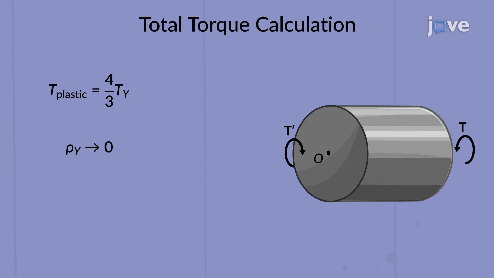
The modulus of rupture represents a fictitious stress value that corresponds to the ultimate torque causing shaft failure. This parameter helps engineers determine the maximum safe operating loads for rotating machinery components. Understanding this concept proves essential for students pursuing mechanical engineering degrees or preparing for the Fundamentals of Engineering (FE) exam.
Real-world applications include designing automotive transmissions, industrial mixer shafts, and wind turbine drive systems where accurate failure prediction prevents catastrophic breakdowns and ensures public safety.
Related Micro-courses