Loading video…


 12 Concepts
 5.2K views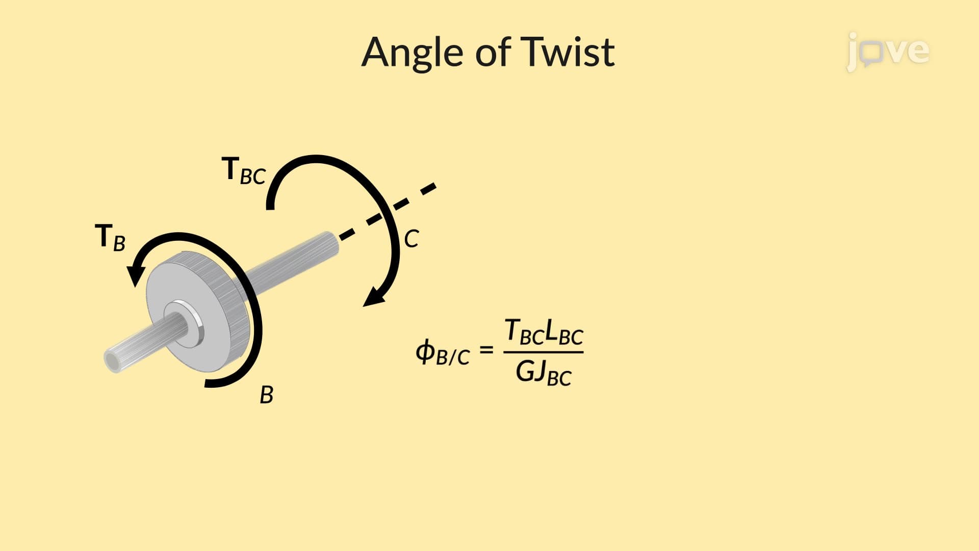

Video Summary: Angle of Twist Problem Solving Explained
Ever wonder why airplane propellers don't snap under massive rotational forces? The answer lies in angle of twist problem solving, a critical engineering principle that predicts how much rotating shafts deform under torque. From Boeing 737 engines to Tesla Model S drive shafts, understanding Angle of Twist Problem Solving Explained helps engineers design safer, more efficient rotating machinery that powers American transportation and industry. Watch the full video on JoVE Coach to master this concept with expert-led visuals and step-by-step explanations.
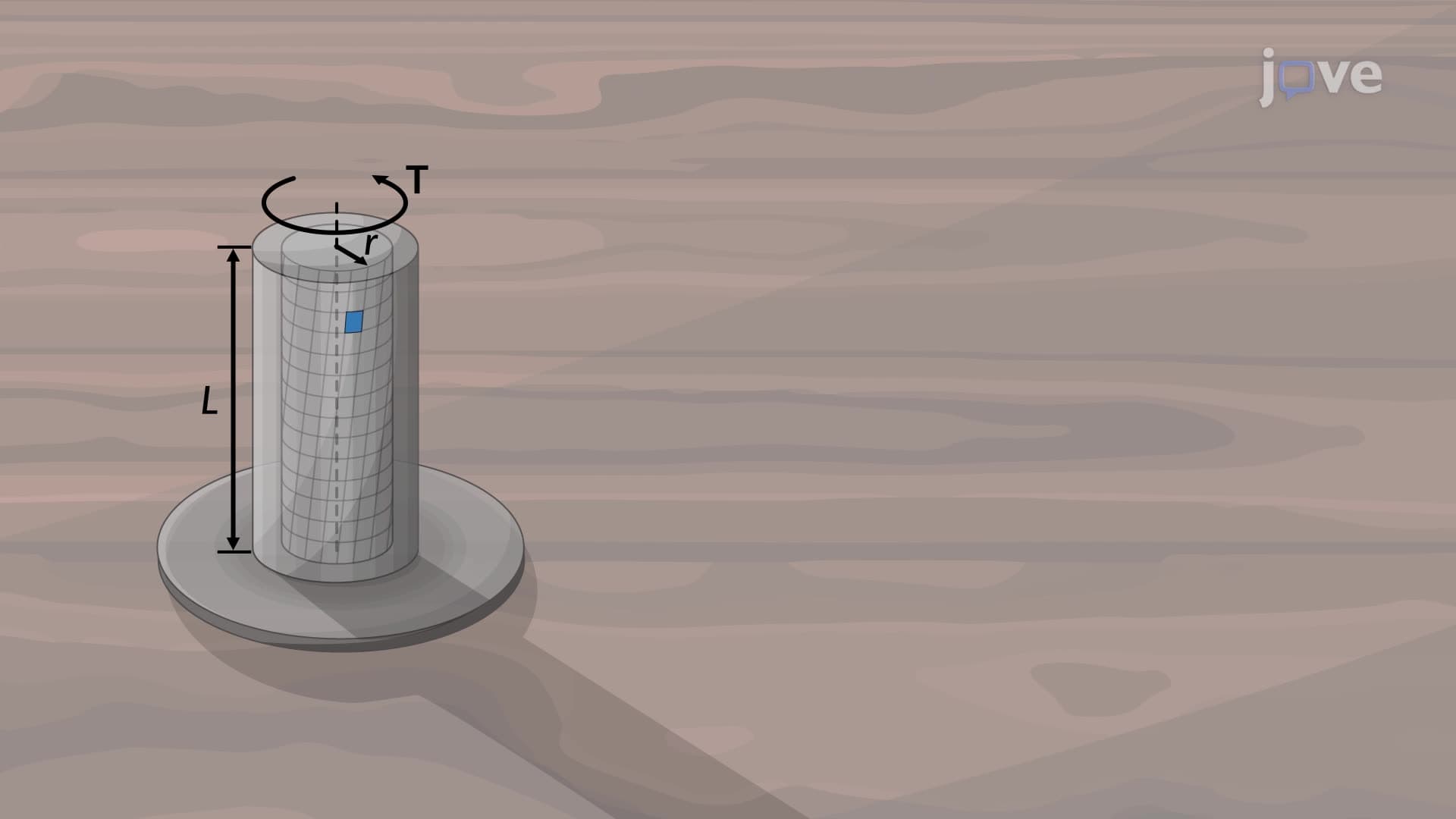
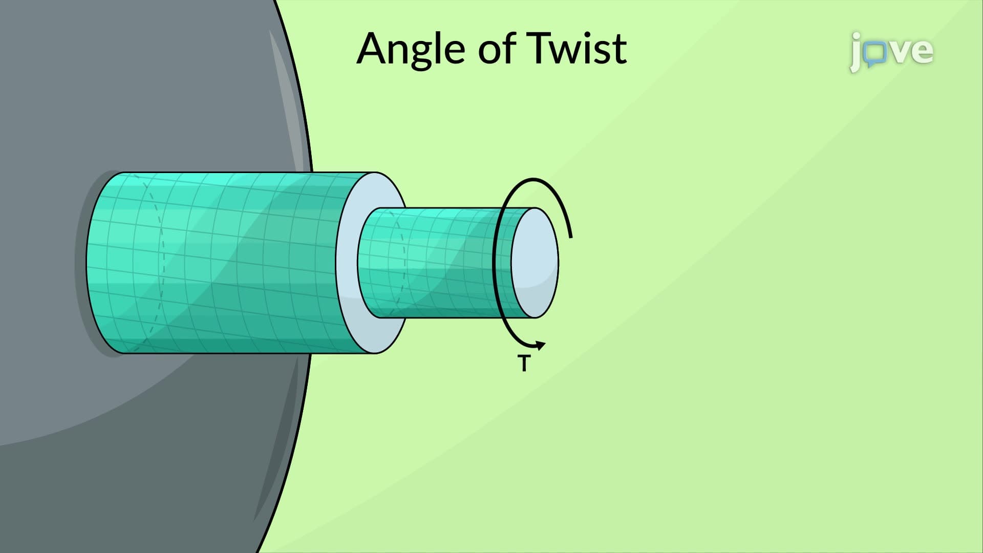
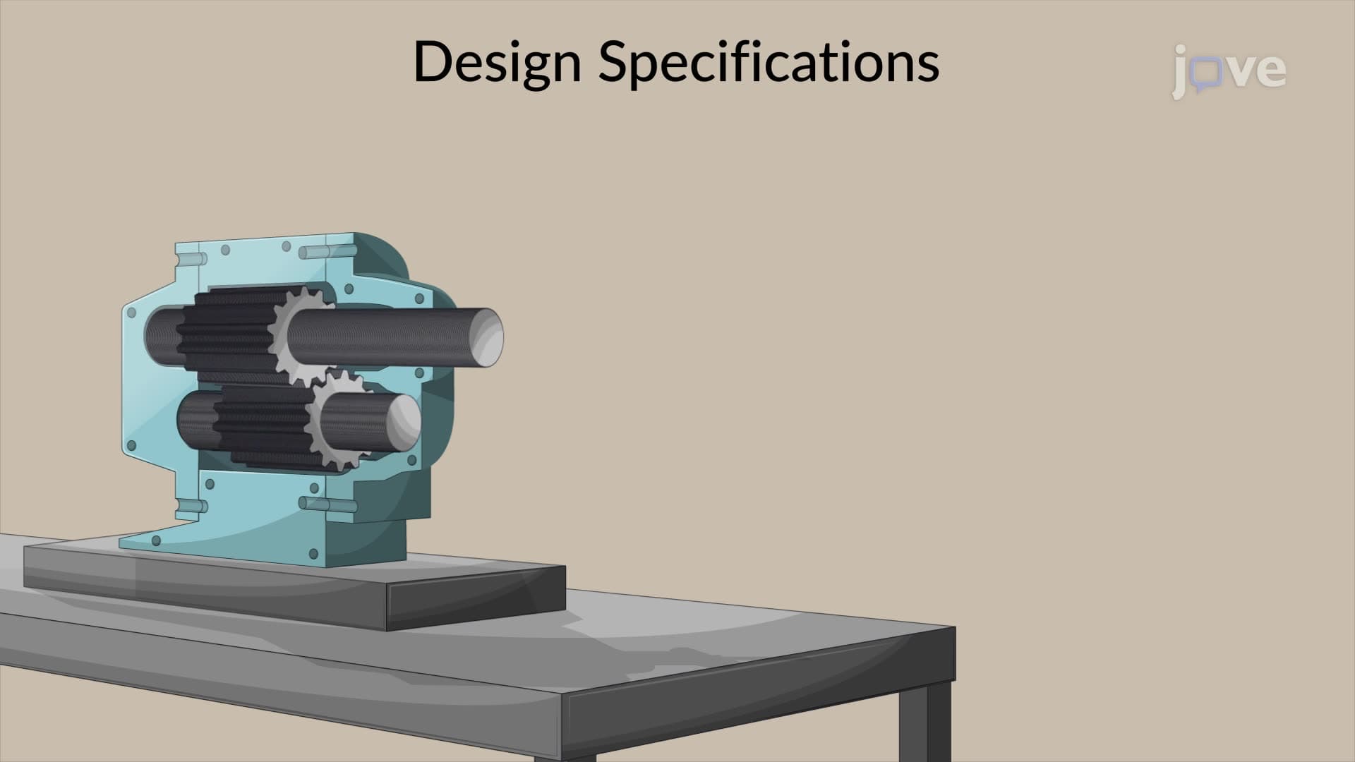
Angle of twist problem solving represents one of the most practical applications of solid mechanics in modern engineering. When rotating shafts transmit power-whether in a Ford F-150's driveshaft or a wind turbine's main rotor-they inevitably twist under applied torques. This angular deformation, measured in radians or degrees, directly impacts performance, safety, and longevity of rotating machinery across American industries.
The fundamental relationship governing shaft twist combines four critical parameters: applied torque (T), shaft length (L), polar moment of inertia (J), and the material's modulus of rigidity (G). Engineers use the formula θ = TL/(GJ) to predict exactly how much a shaft will rotate under load, enabling precise design calculations for everything from helicopter rotors to industrial conveyor systems.
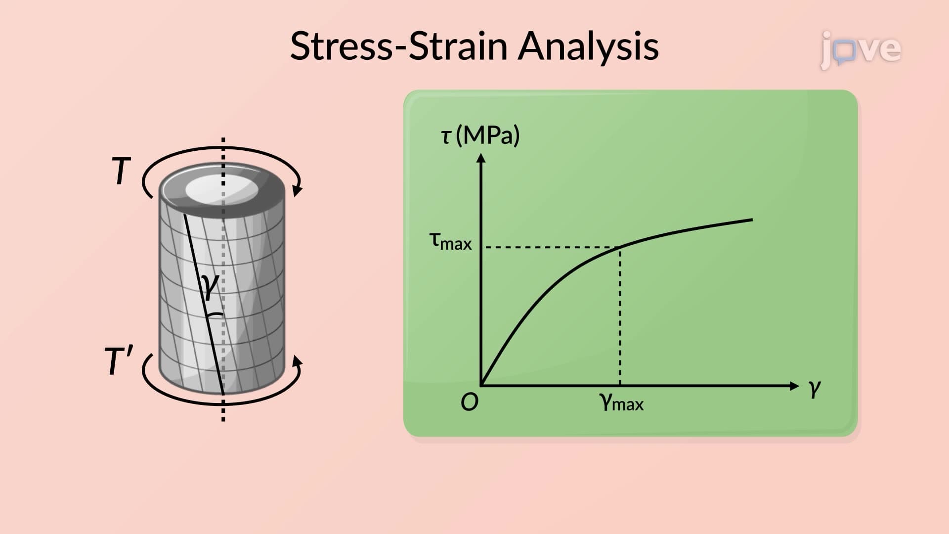
The modulus of rigidity, also called the shear modulus, quantifies a material's resistance to angular deformation. Aluminum alloys commonly used in aerospace applications typically exhibit values around 25-28 GPa, while structural steel reaches approximately 80 GPa. This property directly influences how much a shaft twists under identical loading conditions-critical knowledge for engineers designing everything from NASA rocket engine turbopumps to John Deere tractor transmissions.
Understanding material behavior becomes essential when tackling AP Physics C mechanics problems or undergraduate statics coursework. Students frequently encounter aluminum shaft problems because this material offers an excellent balance of strength, weight, and cost-effectiveness in real-world applications from automotive to aerospace industries.
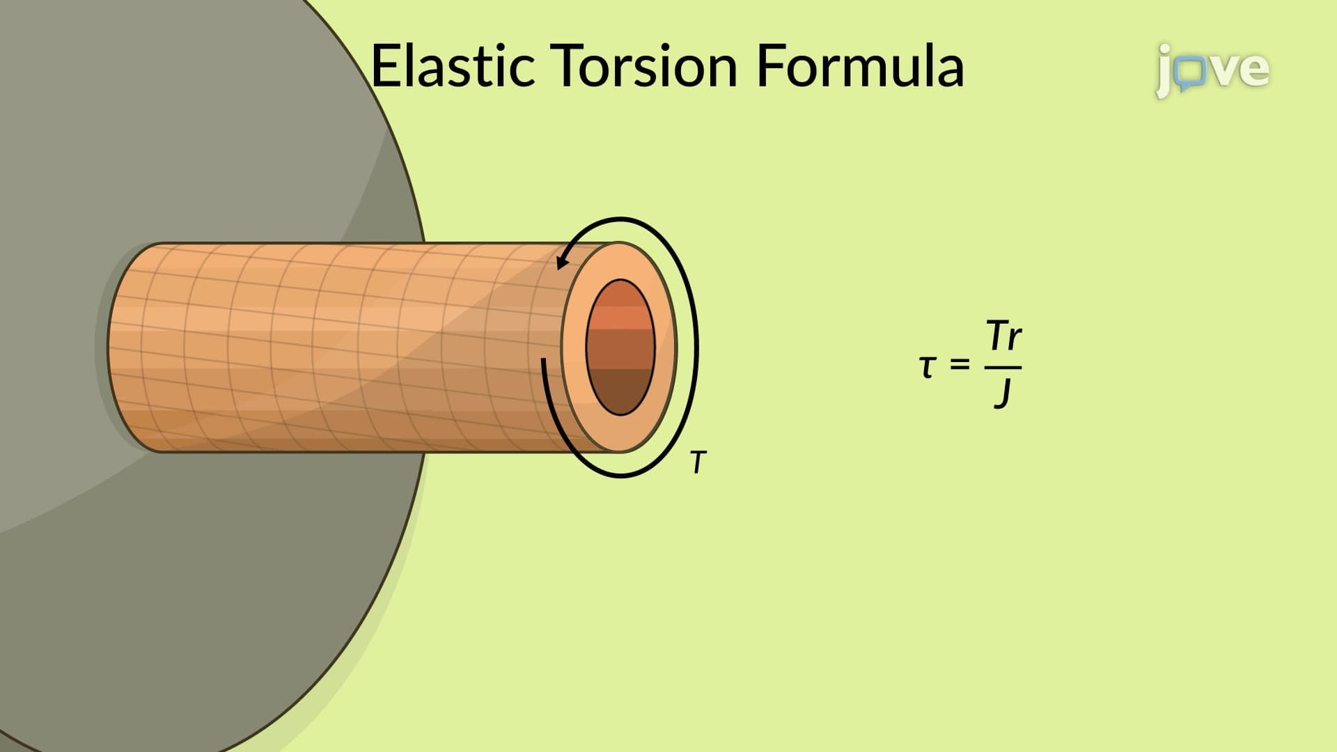
The polar moment of inertia (J) depends entirely on shaft geometry, particularly the fourth power of the radius for solid circular shafts: J = πr⁴/2. This mathematical relationship explains why doubling a shaft's diameter increases its torsional stiffness by a factor of 16-a principle exploited in high-performance applications like Formula 1 racing or military aircraft design.
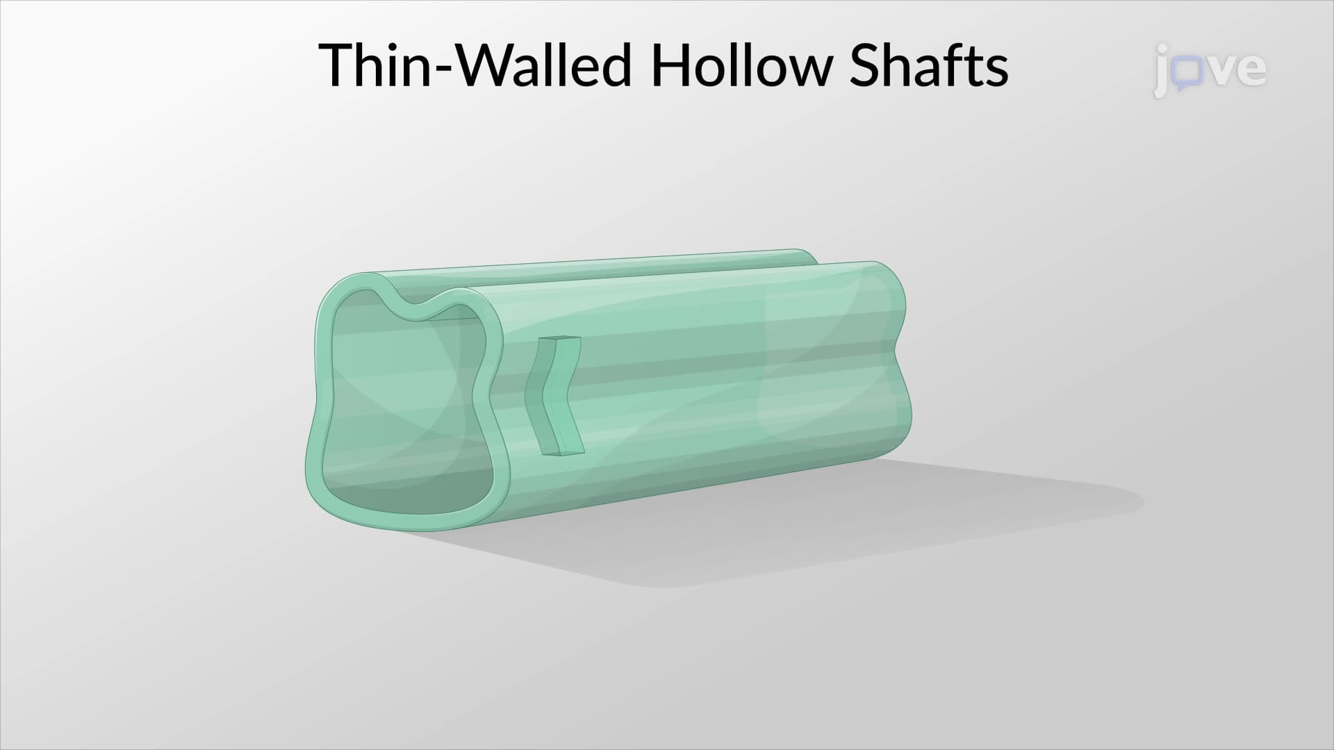
Hollow shafts, commonly found in bicycle frames and aircraft structures, require modified calculations accounting for both outer and inner radii. These weight-optimized designs demonstrate advanced engineering principles frequently tested in college-level mechanics of materials courses and professional engineering examinations.
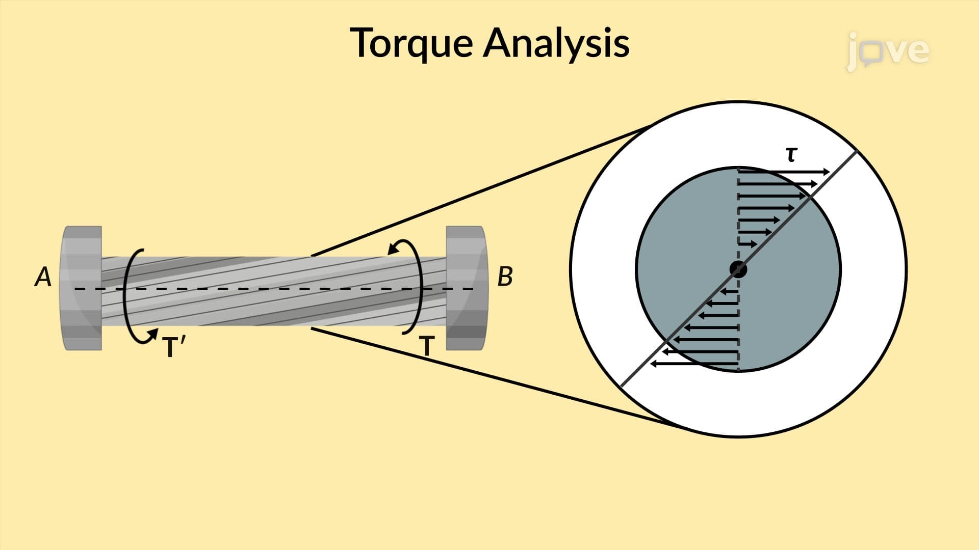
Successful angle of twist problem solving demands systematic application of static equilibrium principles. Engineers create free-body diagrams by making imaginary cuts through shaft cross-sections, then apply the fundamental rule that internal torques must balance external applied torques. This methodology appears consistently in MCAT physics sections, AP Physics C rotational mechanics problems, and undergraduate engineering curricula nationwide.
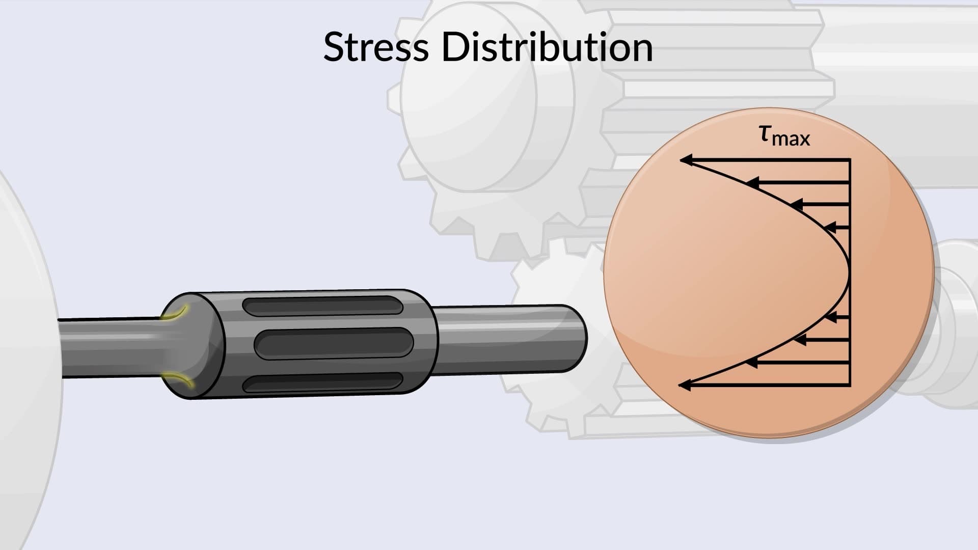
Multi-pulley systems, like those found in automotive serpentine belt drives or industrial manufacturing equipment, require careful analysis of torque distributions. Each pulley introduces or removes torque from the shaft system, creating varying internal stress patterns that directly affect local twist angles-calculations essential for preventing catastrophic failures in critical applications.
Related Micro-courses