Loading video…


 12 Concepts
 5.2K views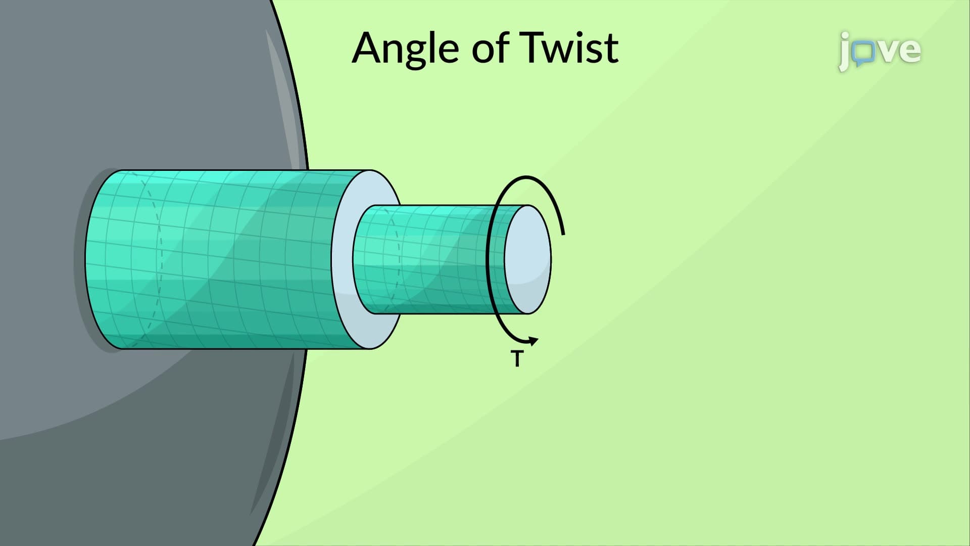

Video Summary: Angle of Twist Elastic Range Explained
Ever wonder why steel bridge cables can withstand massive loads without failing? The angle of twist elastic range determines how much a circular shaft can rotate under torque before permanent deformation occurs. In engineering applications like the Golden Gate Bridge's support cables or automotive drive shafts, understanding this concept prevents catastrophic failures. The Angle of Twist Elastic Range Explained demonstrates the mathematical relationship between applied torque, shaft geometry, and rotational deformation. Watch the full video on JoVE Coach to master this concept with expert-led visuals and step-by-step explanations.
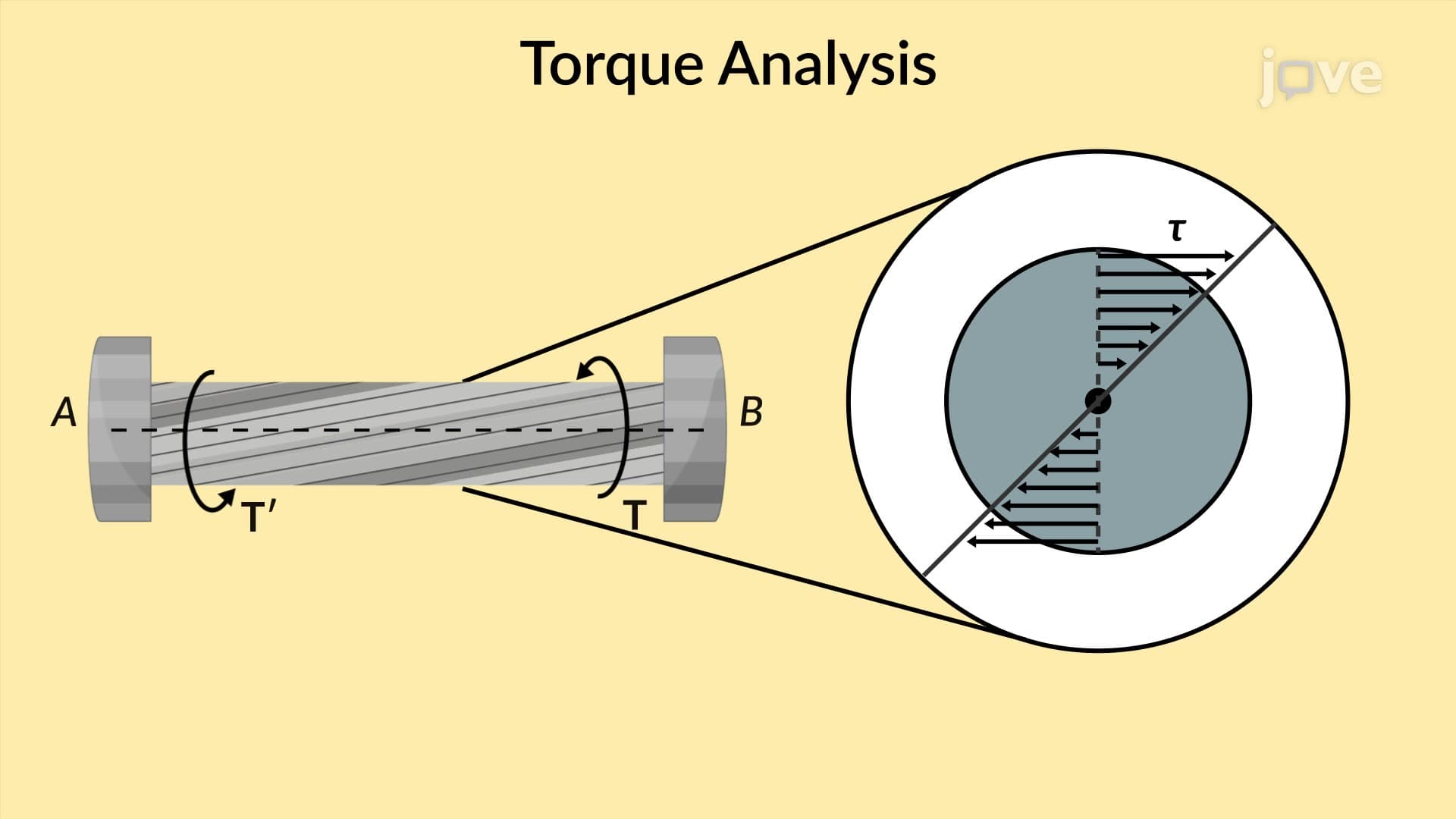
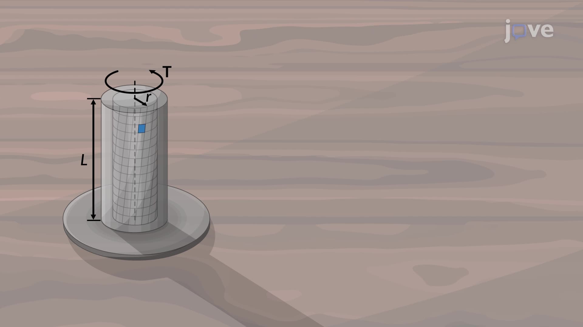
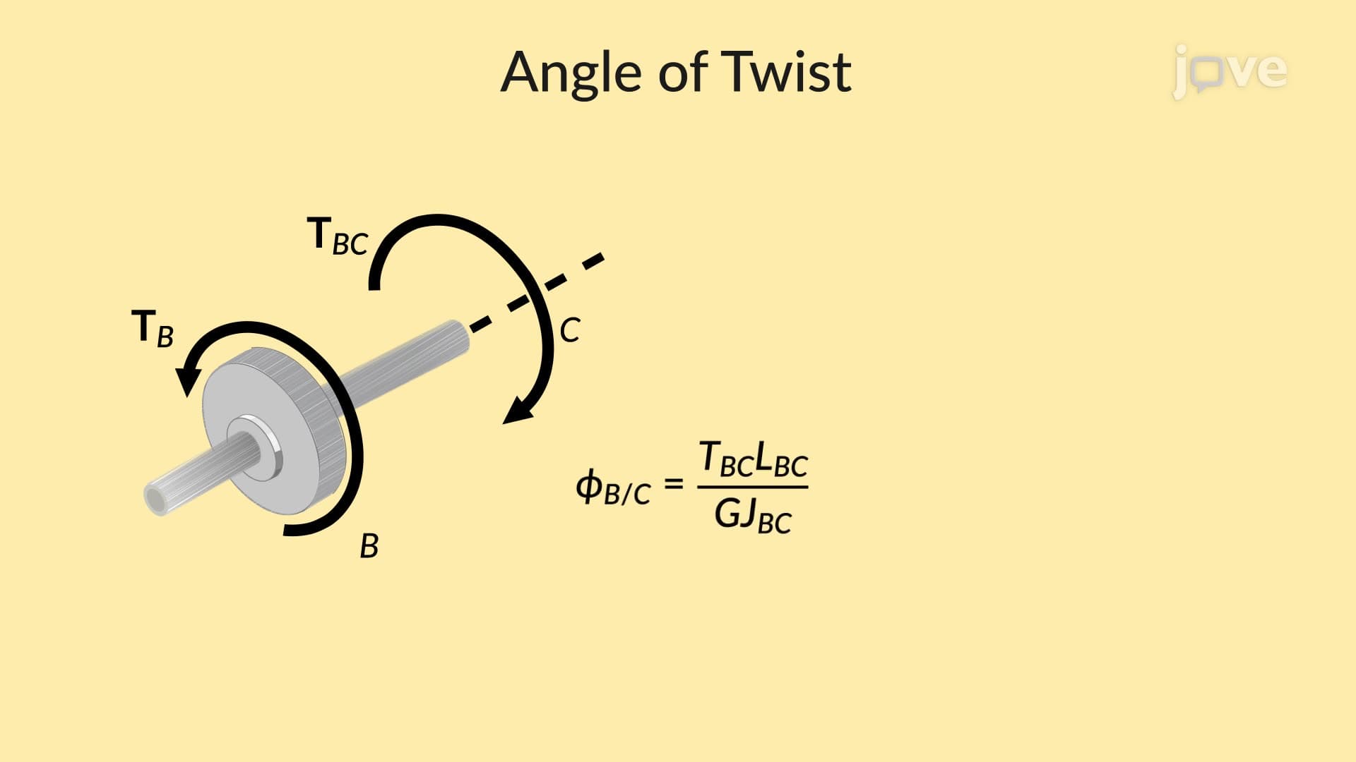
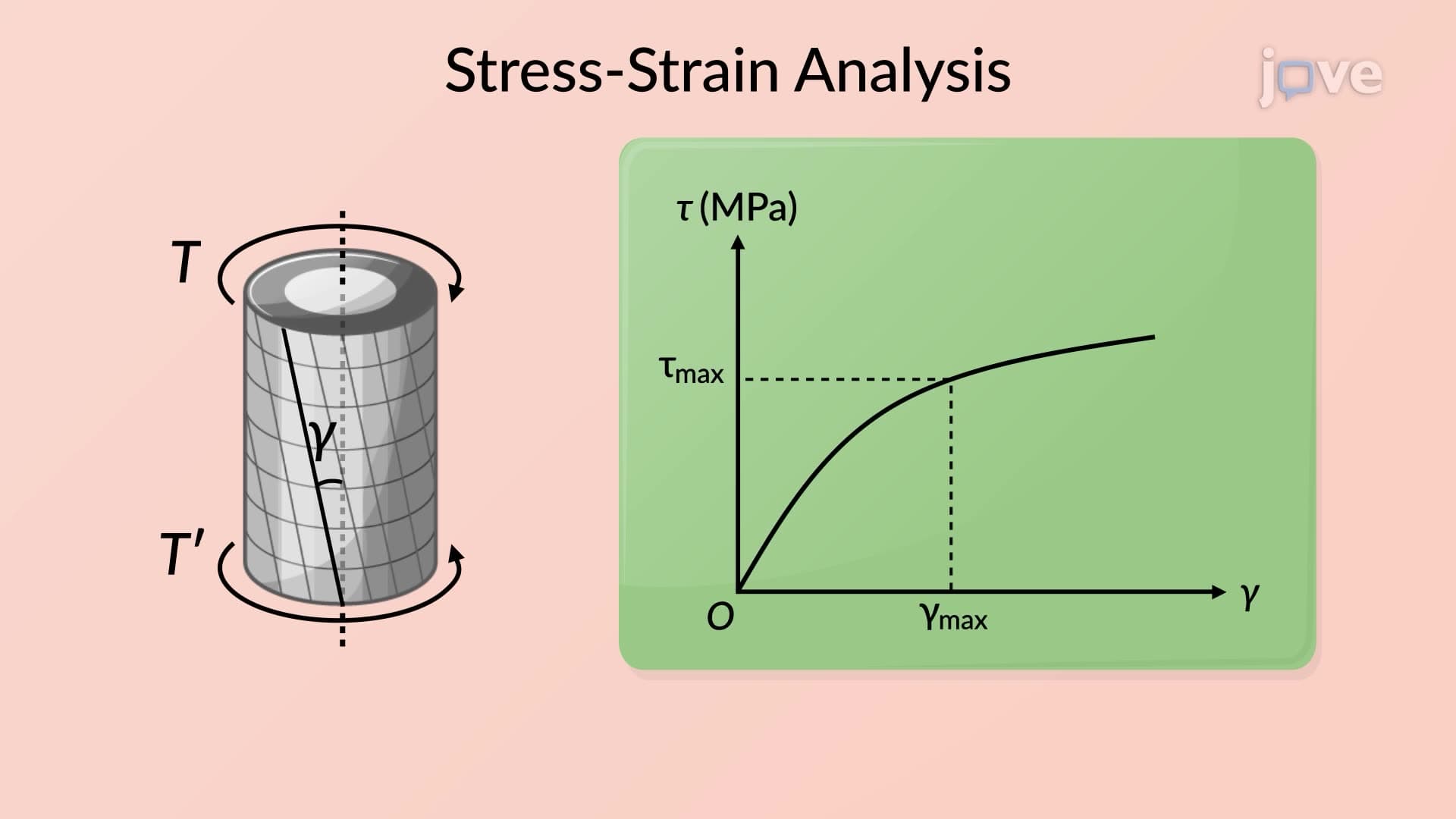
The angle of twist elastic range represents the fundamental relationship governing how circular shafts deform under torsional loading. When a torque is applied to one end of a fixed circular shaft, the shaft rotates through an angle proportional to the applied load, shaft length, and inversely proportional to the shaft's resistance to twisting. This behavior remains linear only within the elastic range, where the material returns to its original shape upon load removal.
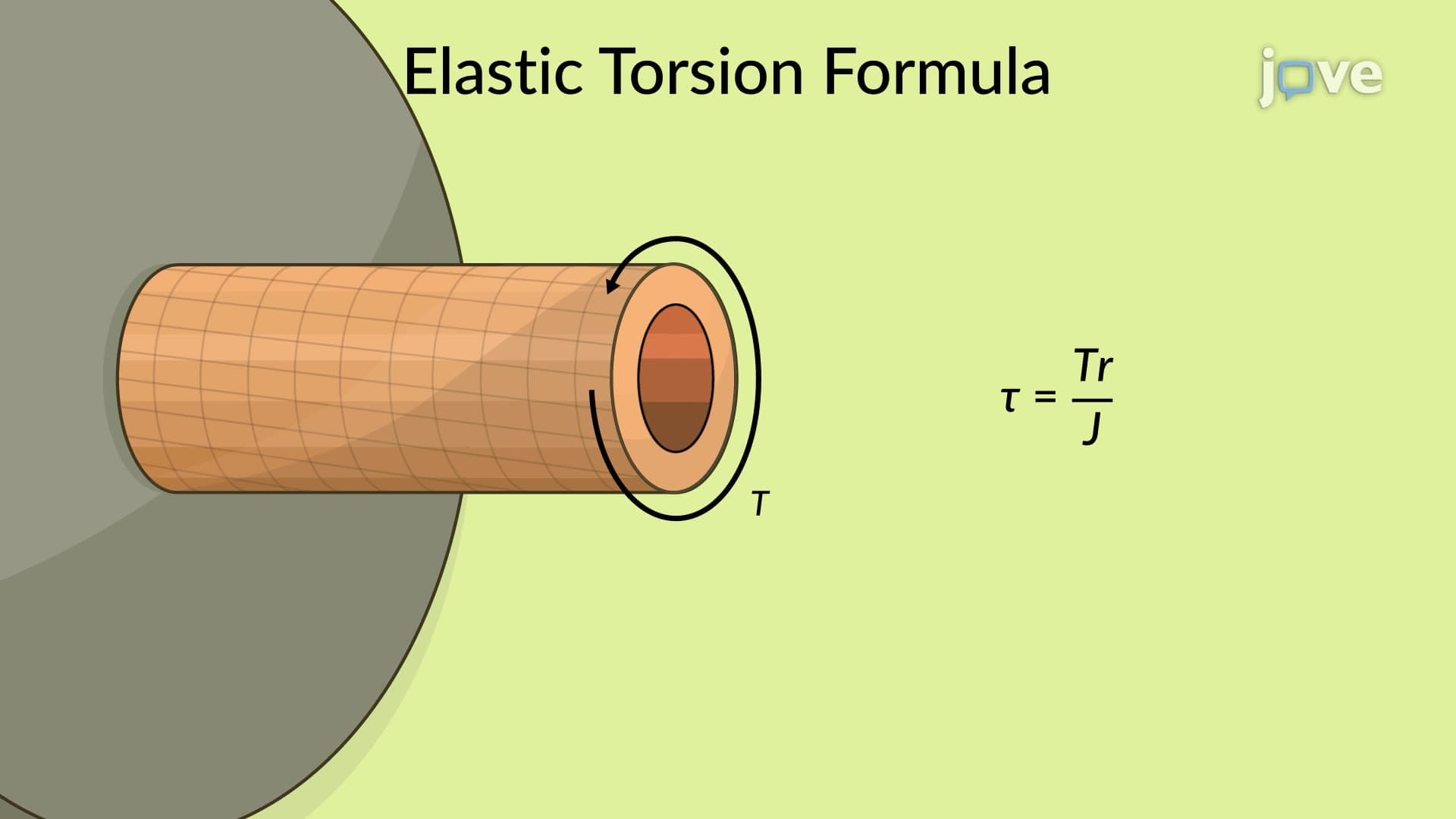
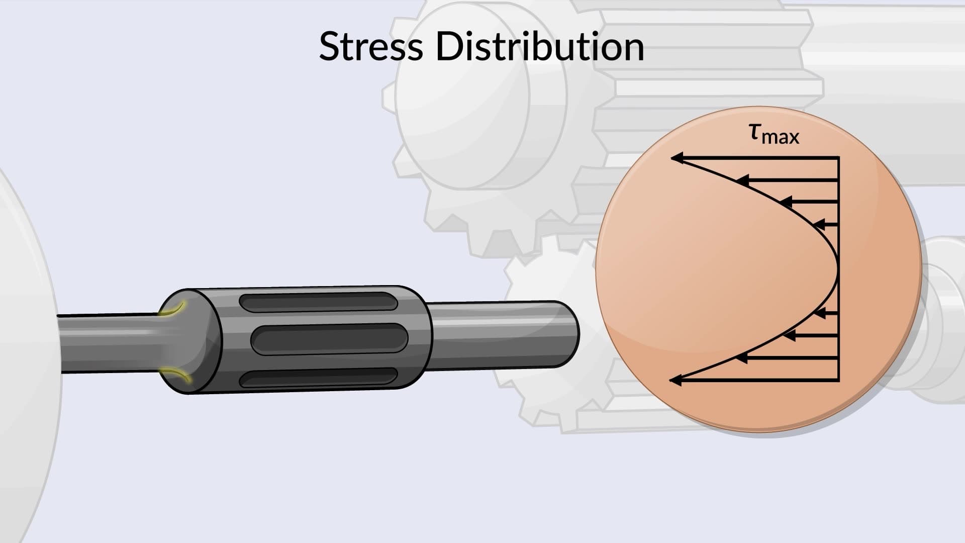
The mathematical foundation rests on the relationship between maximum shearing strain and two key factors: the angle of twist and the radial distance from the shaft's centerline. Maximum shearing strain occurs at the outer fiber of the shaft, where r equals the shaft radius. This strain distribution creates the characteristic linear stress pattern that mechanical engineers rely upon for safe design calculations.
Four critical parameters govern the angle of twist elastic range: applied torque (T), shaft length (L), polar moment of inertia (J), and modulus of rigidity (G). The polar moment of inertia depends entirely on the shaft's geometry-for solid circular shafts, J = πr⁴/2, while hollow shafts use J = π(r₄⁴ - r₁⁴)/2. The modulus of rigidity varies by material: steel typically ranges from 80-85 GPa, while aluminum averages 26-28 GPa.
Understanding these relationships proves essential for AP Physics C mechanics problems and college-level statics courses. Students frequently encounter twist angle calculations on mechanical engineering licensing exams, where proper unit conversion and formula application determine success.
Real-world applications rarely involve simple, uniform shafts with single point loads. Automotive drive shafts experience multiple torques from engine output, transmission loads, and wheel resistance. In such cases, engineers apply superposition principles, calculating individual twist angles for each shaft segment and summing the results.
Consider a Boeing 737's propeller shaft system, where different shaft diameters, materials, and loading points require segmented analysis. Each section between torque application points must be analyzed separately, then combined to determine total angular displacement. This approach ensures structural integrity while optimizing weight and material costs.
The angle of twist elastic range concept appears throughout American infrastructure and manufacturing. Wind turbine generators rely on precise twist calculations to prevent blade-to-tower interference during high-wind conditions. Similarly, oil drilling equipment must account for torsional deformation in drill strings extending thousands of feet underground, where twist accumulation could cause directional drilling errors or equipment failure.
Related Micro-courses