13 Concepts
10 Concepts
17 Concepts
6 Concepts
20 Concepts
9 Concepts
17 Concepts
14 Concepts
19 Concepts
13 Concepts
12 Concepts
12 Concepts
4 Concepts
5 Concepts
12 Concepts
13 Concepts
10 Concepts
8 Concepts
20 Concepts
12 Concepts
18 Concepts
4 Concepts
6 Concepts
10 Concepts
4 Concepts
9 Concepts
7 Concepts
8 Concepts
Shearing stresses in beams and thin-walled members represent critical forces that structural engineers must calculate to ensure safe building designs. This JoVE Coach micro-course explores how horizontal and vertical shear forces create stress distributions throughout beam cross-sections, from simple rectangular beams to complex thin-walled channels used in American construction projects like steel-framed buildings and highway overpasses.
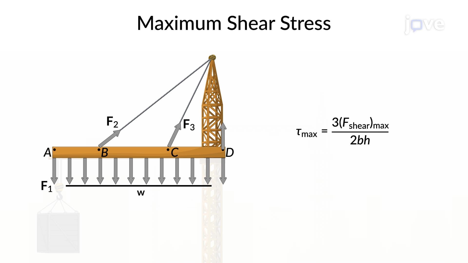
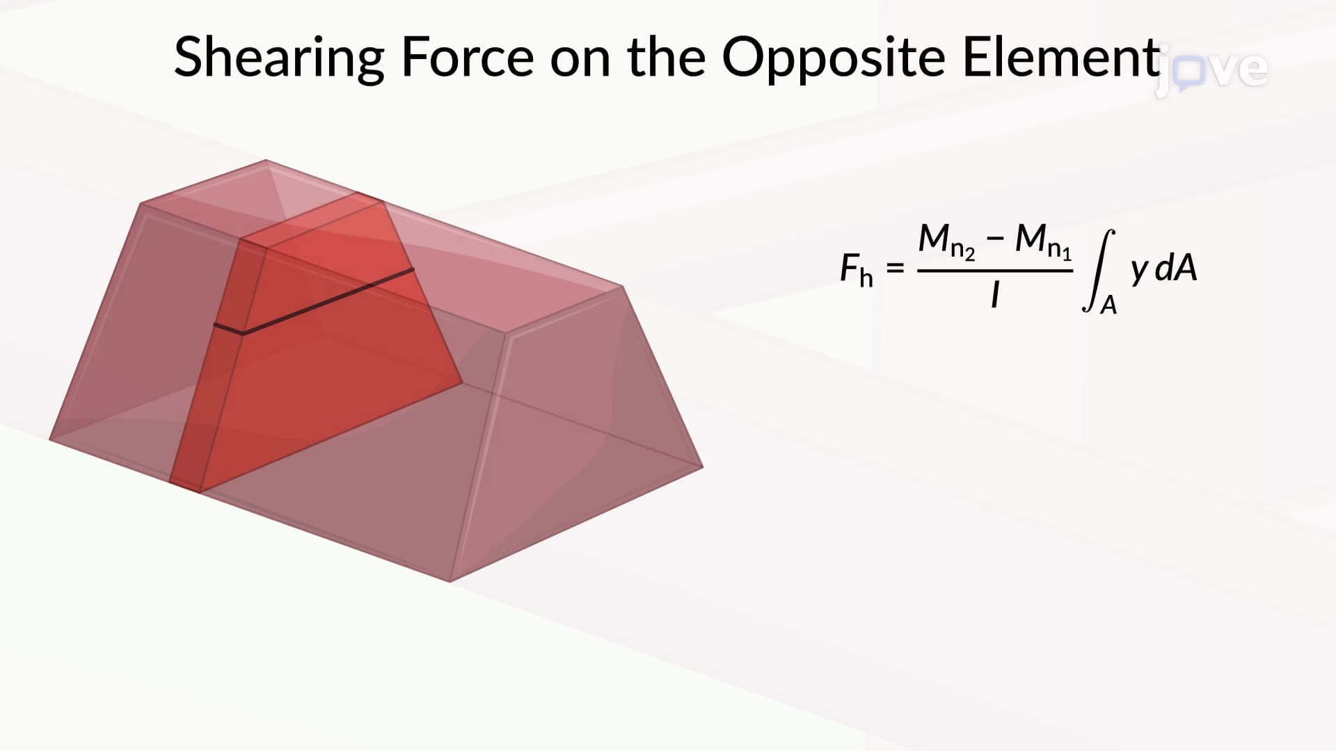
1. Horizontal Shear Force Development: When beams experience vertical loading, horizontal shearing forces develop between adjacent layers of the beam material. Using equilibrium equations, these internal forces can be calculated by analyzing small beam elements and considering the balance of bending moments. The horizontal shear equals the product of vertical shear force, first moment of area, and the reciprocal of moment of inertia. This relationship applies to common American construction materials like steel I-beams used in skyscrapers or wooden joists in residential construction. Understanding this concept helps engineers design safe floor systems and bridge girders.
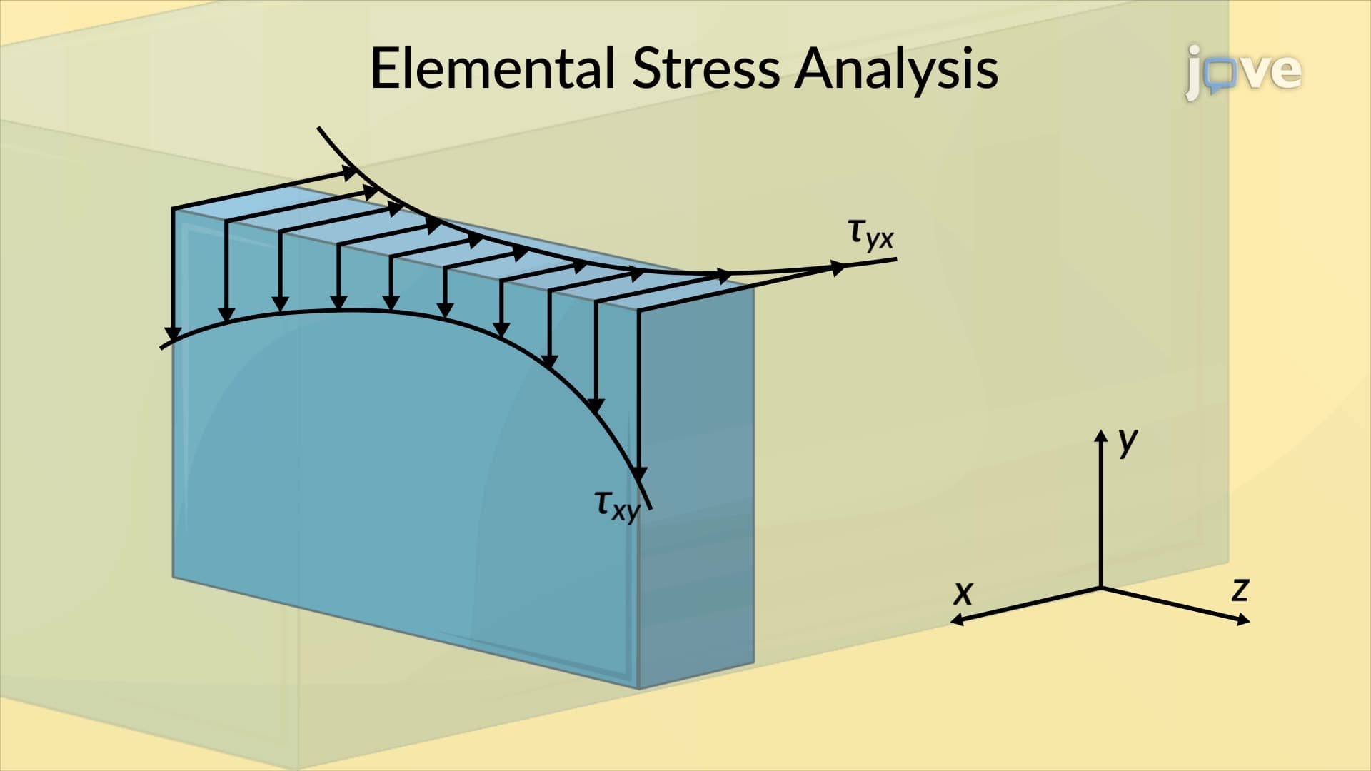
2. Shear Stress Distribution in Rectangular Beams: In narrow rectangular cross-sections where width is less than one-quarter of the depth, shear stress varies minimally across the width (less than 0.8% variation). The stress distribution follows a parabolic pattern through the beam height, with zero stress at the top and bottom surfaces and maximum stress at the neutral axis. This principle applies to wooden beams in residential construction and concrete beams in commercial buildings. American building codes rely on these calculations to establish safe loading limits for structural members.
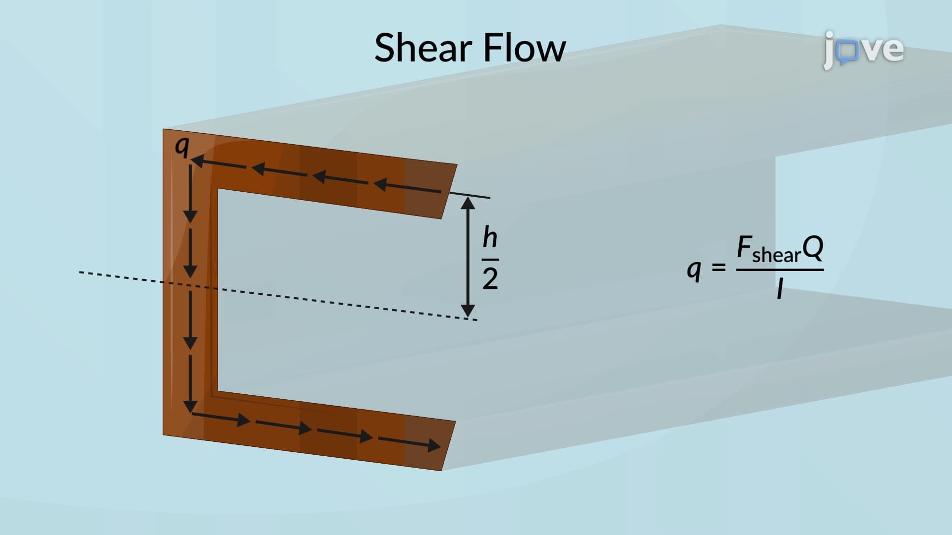
3. Shear Flow in Thin-Walled Members: Shear flow represents the shear force per unit length along thin-walled sections like steel channels and angles commonly used in American construction. By integrating shear flow around the cross-section perimeter, engineers determine internal force distributions. This concept is crucial for designing lightweight structures such as aircraft wings, where aluminum channels carry substantial loads, and steel-framed buildings where efficiency demands thin-walled sections. The shear flow calculation helps optimize material usage while maintaining structural integrity.
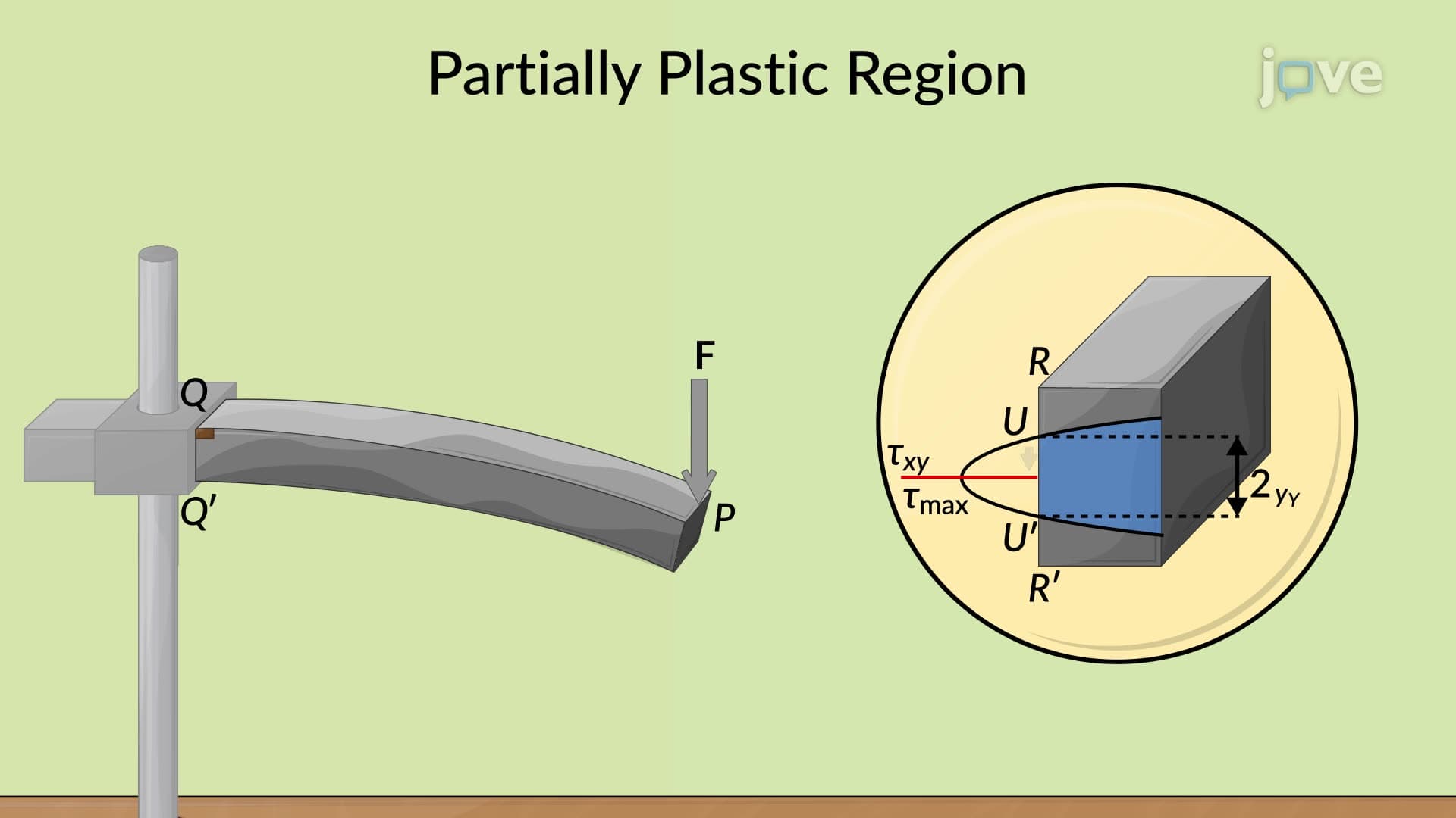
4. Plastic Deformation and Ultimate Strength: When beams exceed their elastic limit, plastic zones develop starting from points of maximum moment, typically near fixed supports in cantilever beams. As loading increases, plastic hinges form where the entire cross-section yields, representing the ultimate load capacity. In the plastic region, shear stress concentrates in the remaining elastic core, potentially reaching yield strength and contributing to failure. This behavior is critical for understanding seismic design of buildings in earthquake-prone areas like California, where structures must survive extreme loading conditions.
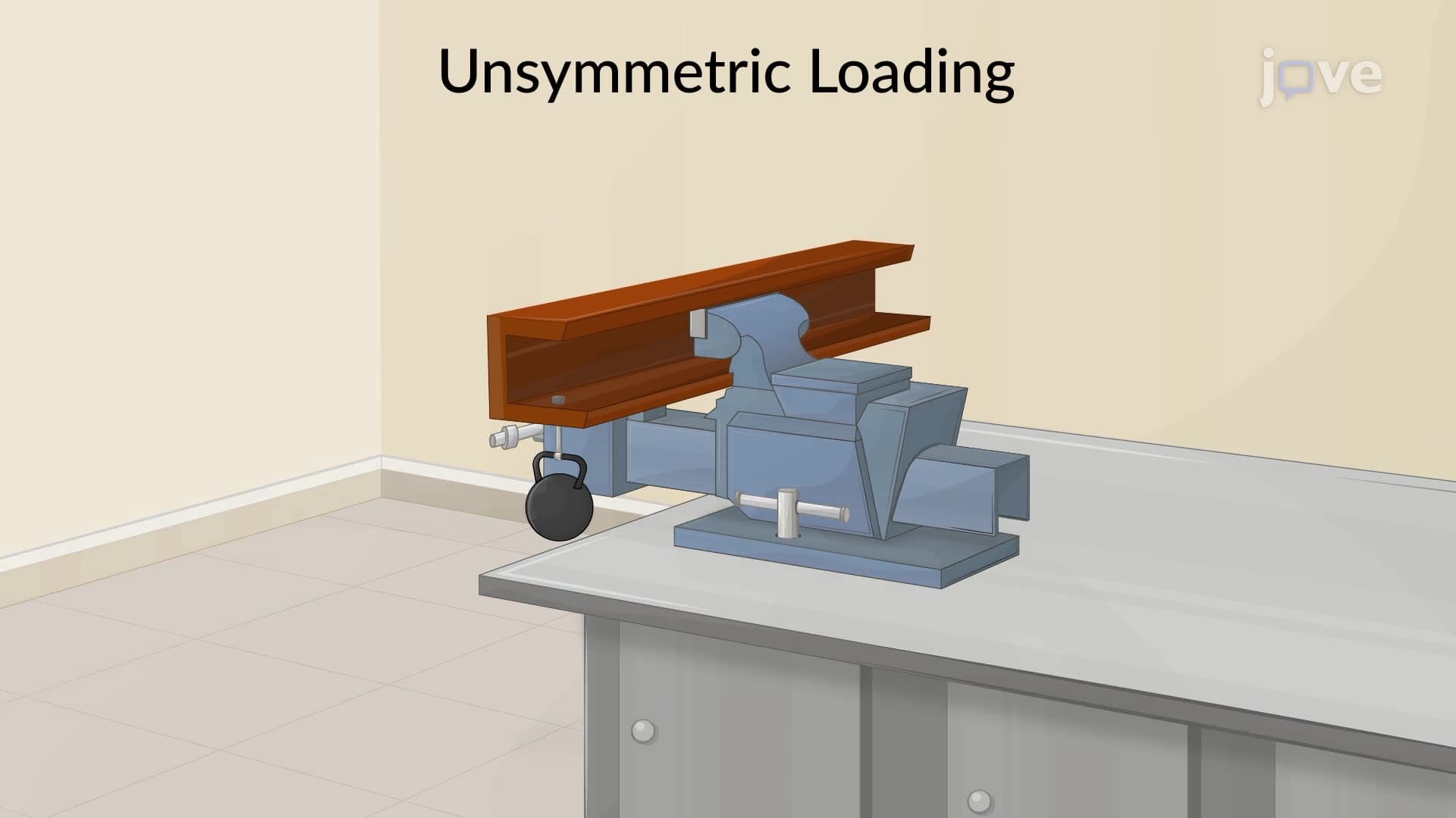
5. Shear Center and Unsymmetric Loading: The shear center represents the point where applied loads cause only bending without twisting in thin-walled members. For channel sections commonly used in American steel construction, the shear center lies outside the cross-sectional area. When loads are applied away from the shear center, members experience combined bending and torsion, potentially leading to lateral-torsional buckling. This concept is essential for designing crane runway beams, bridge girders, and building columns where eccentric loading is unavoidable.