13 Concepts
10 Concepts
17 Concepts
6 Concepts
20 Concepts
9 Concepts
17 Concepts
14 Concepts
19 Concepts
13 Concepts
12 Concepts
12 Concepts
4 Concepts
5 Concepts
12 Concepts
13 Concepts
10 Concepts
8 Concepts
20 Concepts
12 Concepts
18 Concepts
4 Concepts
6 Concepts
10 Concepts
4 Concepts
9 Concepts
7 Concepts
8 Concepts
Transformations of stress and strain represent fundamental concepts in engineering mechanics, examining how stress and strain components change when coordinate systems rotate. This comprehensive course covers principal stress analysis, maximum shear stress calculations, and Mohr's circle applications-essential tools for analyzing structural components in bridges, aircraft, and mechanical systems. Students master both two-dimensional and three-dimensional analysis techniques using JoVE Coach's visual approach.
1. Plane Stress Transformation Fundamentals: Understanding how normal and shear stress components change when a stress element rotates through an angle θ. The transformation equations σ' = (σx + σy)/2 + (σx - σy)/2·cos(2θ) + τxy·sin(2θ) demonstrate this relationship mathematically. These concepts apply directly to analyzing stress in structural beams, pressure vessels, and mechanical components where loading occurs in multiple directions, such as aircraft wing structures or building frameworks under combined bending and torsional loads.
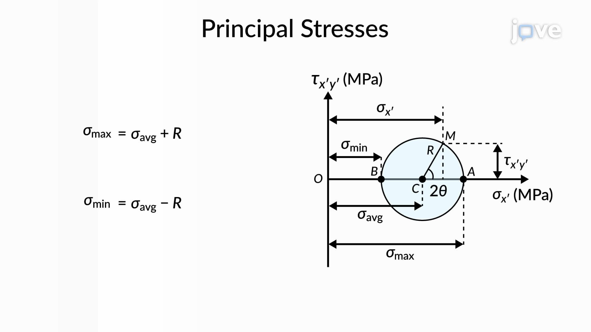
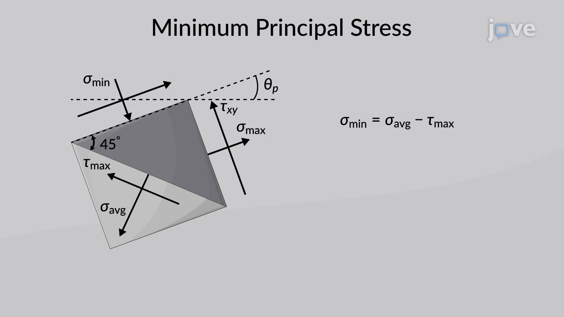
2. Principal Stress Analysis and Applications: Principal stresses represent the maximum and minimum normal stresses occurring at a point, with zero shear stress on these planes. The principal stress values are σ1,2 = (σx + σy)/2 ± √[(σx - σy)/2)² + τxy²]. Engineers use principal stress analysis to design critical components like turbine blades, bridge connections, and pressure vessel walls where failure typically initiates along principal stress directions. Understanding that principal planes are oriented 45° from maximum shear stress planes is crucial for failure analysis.
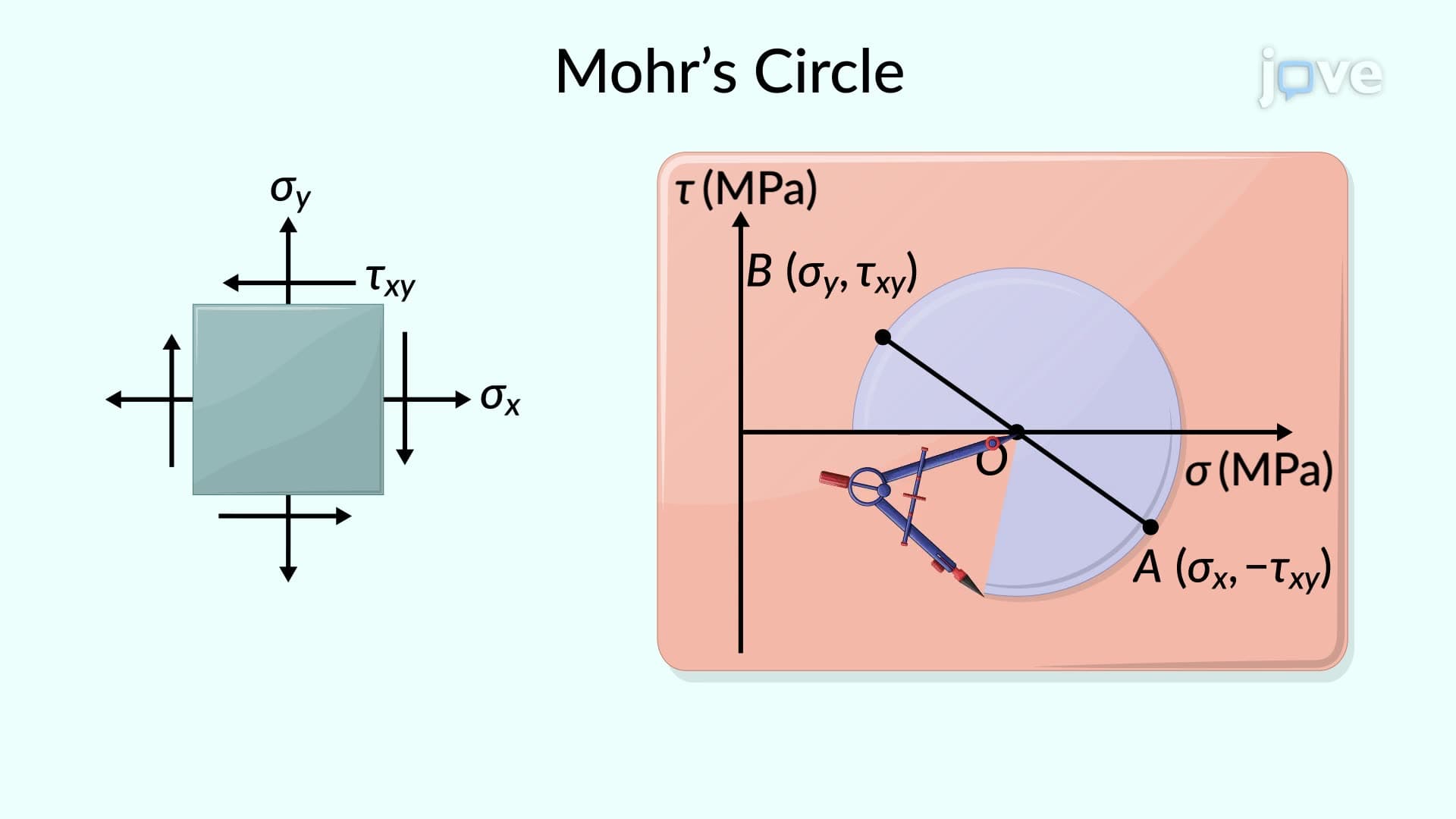
3. Mohr's Circle Construction and Interpretation: Mohr's circle provides a powerful graphical method for visualizing stress transformations, with normal stress plotted on the horizontal axis and shear stress on the vertical axis. The circle's center represents average normal stress (σx + σy)/2, while its radius equals the maximum shear stress. This technique is extensively used in geotechnical engineering for soil stress analysis, structural engineering for beam design, and mechanical engineering for shaft analysis. The graphical approach helps students understand stress relationships intuitively.
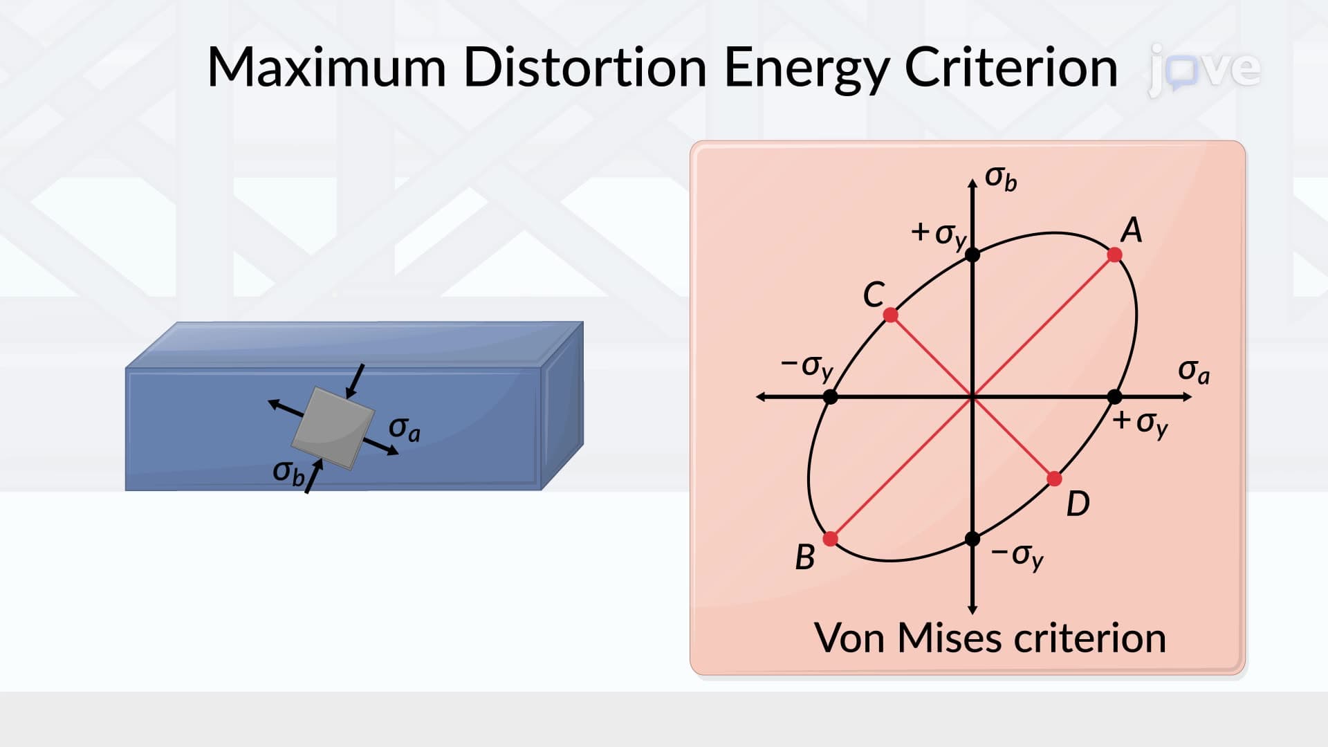
4. Maximum Shear Stress and Yield Criteria: Maximum shear stress occurs on planes 45° from principal planes and equals half the difference between principal stresses: τmax = (σ1 - σ2)/2. Engineers apply yield criteria like Tresca (maximum shear stress) and von Mises (distortion energy) to predict material failure under biaxial stress conditions. These criteria are essential for designing automotive components, aerospace structures, and industrial machinery where complex loading patterns exist, ensuring components remain within safe operating limits.
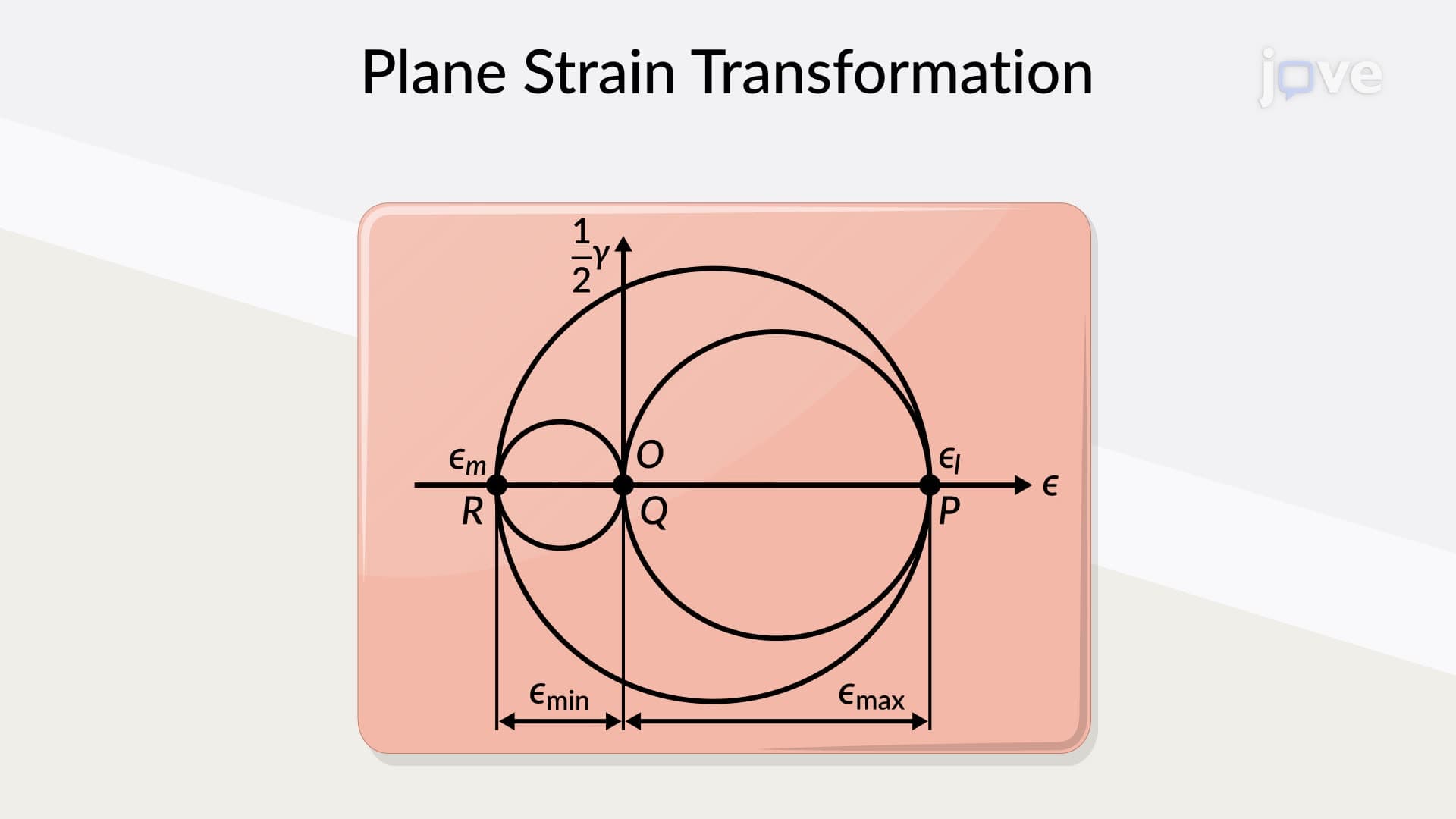
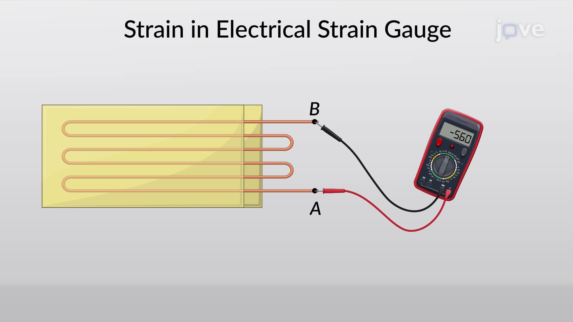
5. Strain Transformations and Measurement Techniques: Similar to stress transformations, strain components change with coordinate rotation following equations parallel to stress transformation. Electrical strain gauges measure normal strains by detecting resistance changes in thin wires bonded to materials. Strain rosettes (typically 45° or 60° configurations) measure strains in multiple directions to determine complete strain states. These measurement techniques are crucial in experimental stress analysis for validating theoretical predictions in structures like suspension bridges, aircraft fuselages, and automotive chassis components.