Loading subject page…


6,613 views

Video Summary: Mohrs Circle for Plane Stress Explained
Ever wonder how civil engineers determine if a skyscraper beam in New York can handle wind forces from multiple directions? Mohr's circle for plane stress provides the graphical solution that transforms complex stress calculations into visual insights. This powerful engineering tool helps analyze stress components acting on structural elements like steel beams in bridges or aircraft wings. By plotting stress states on a coordinate system, engineers can instantly identify maximum stress conditions and failure planes. Watch the full video on JoVE Coach to master this concept with expert-led visuals and step-by-step explanations.
Mohr's circle represents one of the most elegant solutions in engineering mechanics, transforming complex algebraic stress transformation equations into intuitive geometric relationships. Named after German engineer Otto Mohr, this graphical method allows engineers to visualize how stress components change as we rotate a structural element through different orientations.
The foundation lies in recognizing that any stressed element experiences normal stresses (perpendicular to surfaces) and shear stresses (parallel to surfaces). These stress components vary depending on the orientation we choose to examine the element. Mohr's circle captures all possible stress combinations for every orientation in a single, comprehensive diagram.
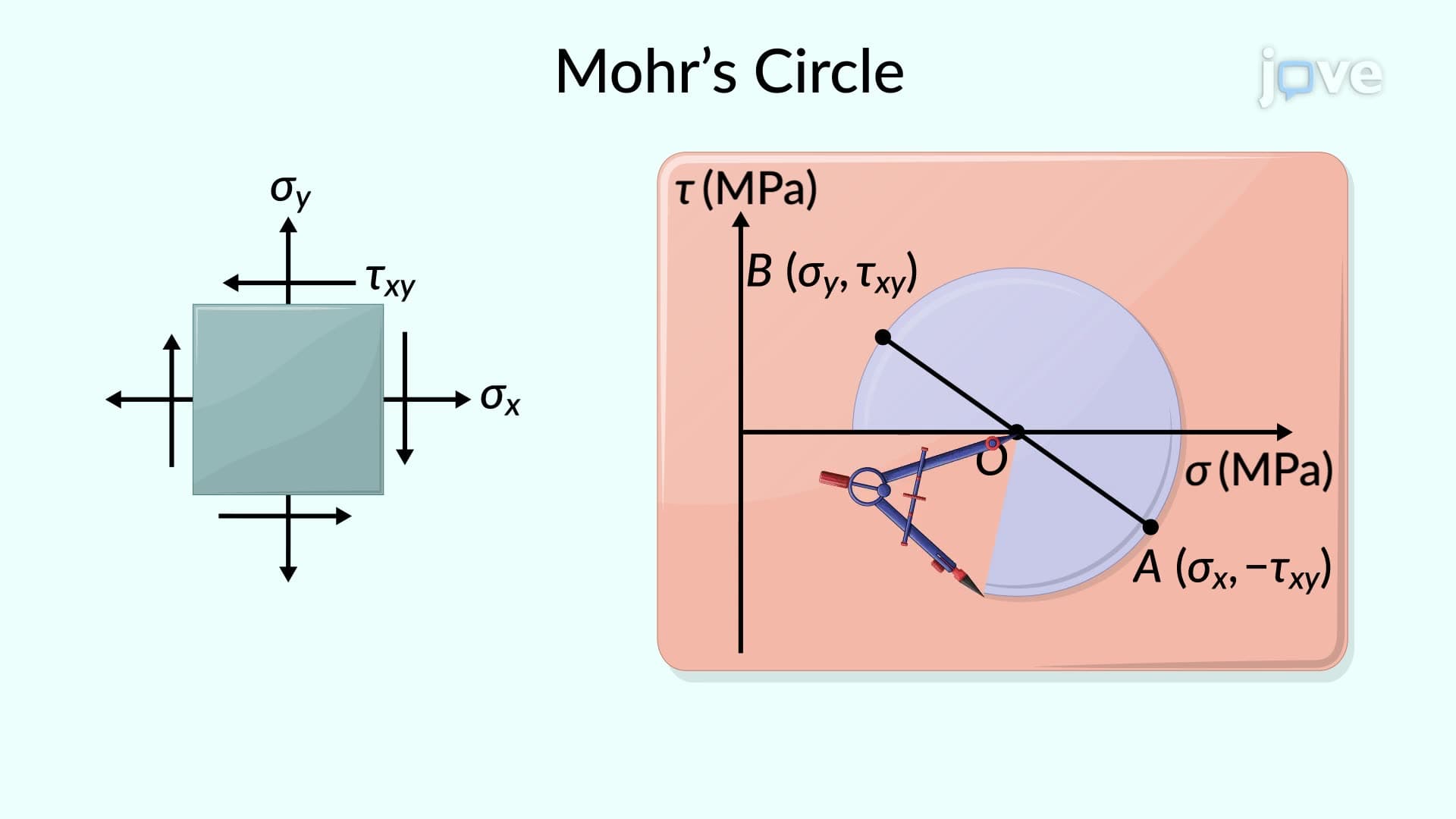
The construction process begins by identifying stress components on perpendicular faces of a square element. Each face contributes a coordinate point: normal stress provides the horizontal (x-axis) position, while shear stress determines the vertical (y-axis) position. The sign convention proves crucial-positive shear stress places points below the horizontal axis, while negative shear stress positions them above.
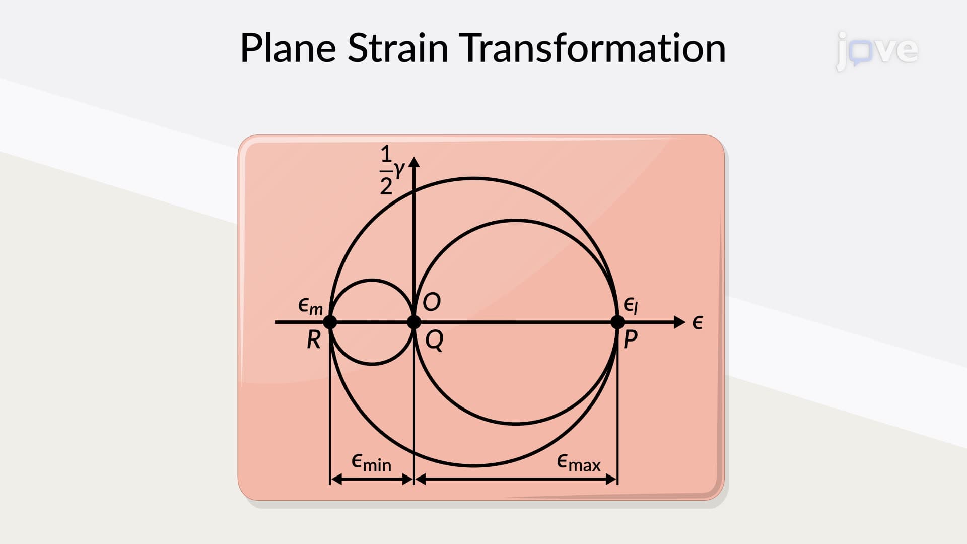
The circle's center lies at the midpoint between these two plotted points, always positioned on the horizontal axis. This geometric constraint ensures that complementary faces of the element maintain their mathematical relationship. The diameter connecting the two stress points defines the complete circle, creating a powerful visualization tool.
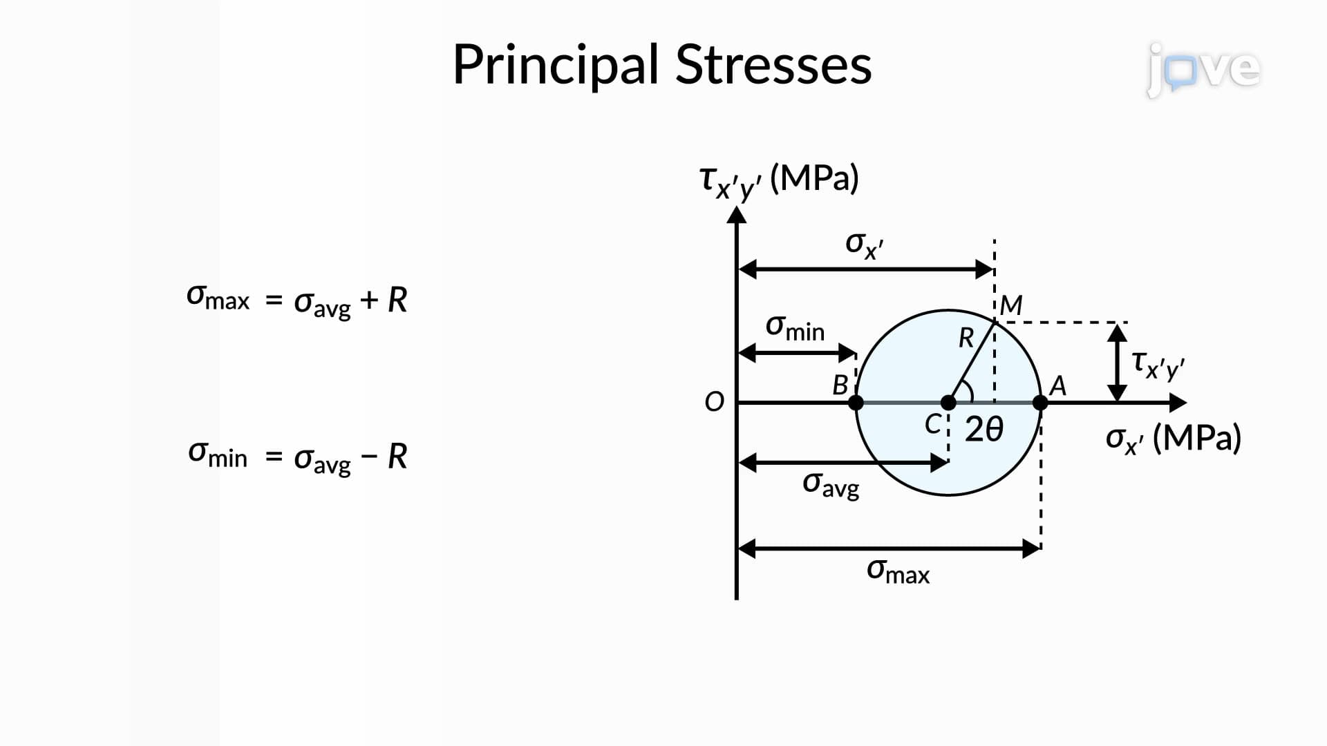
The circle's intersections with the horizontal axis reveal the principal stresses-the maximum and minimum normal stresses the element experiences. These points represent orientations where shear stress equals zero, critical for understanding potential failure modes. In structural applications like bridge design, engineers must ensure materials can withstand these peak stress conditions.
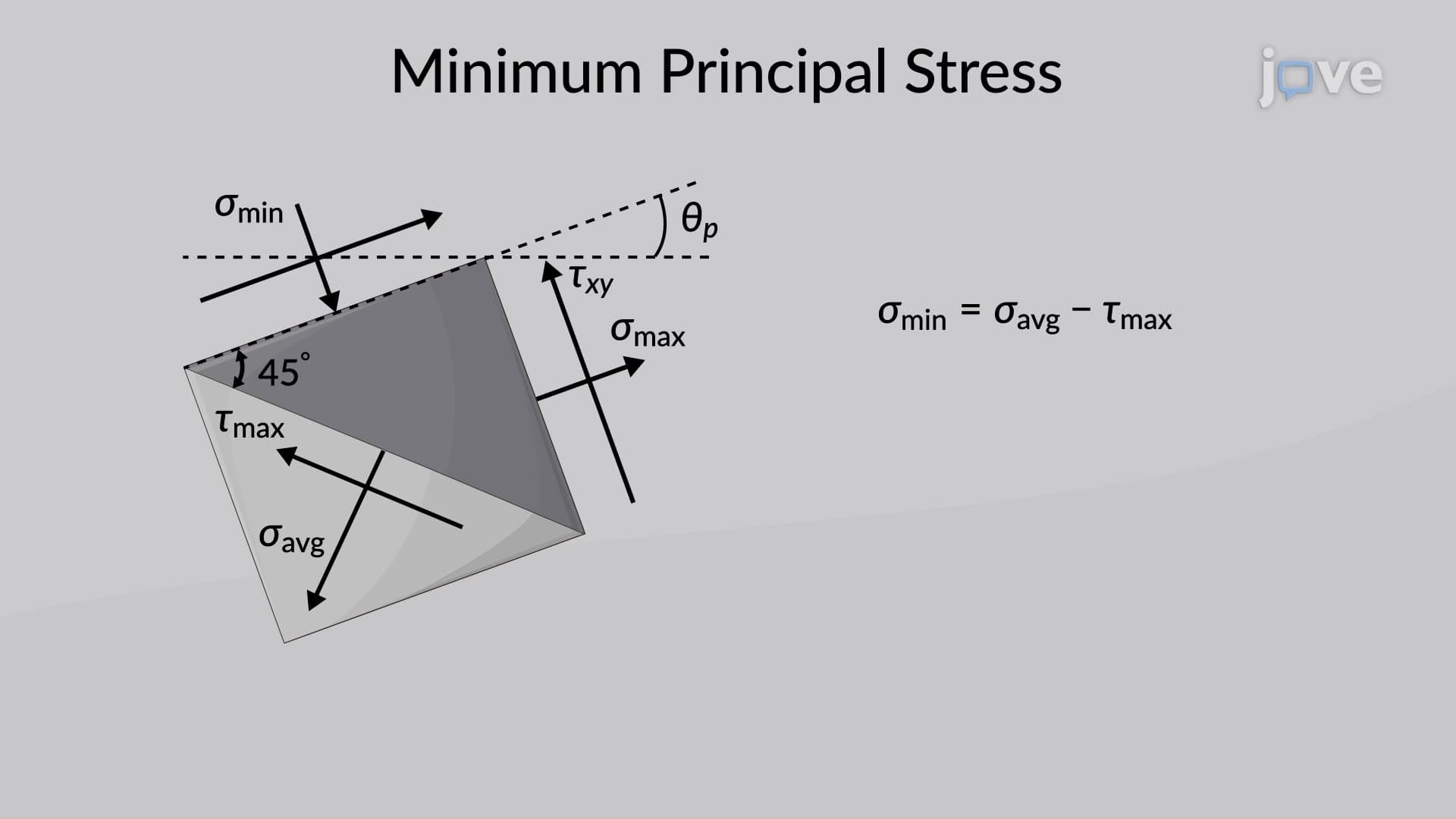
The circle's radius directly corresponds to the maximum shear stress, occurring at orientations 45 degrees from the principal stress directions. This relationship proves essential in failure analysis, as many materials fail in shear before reaching their normal stress limits. For example, steel beams in earthquake-resistant buildings must account for maximum shear stresses during seismic events.
Students preparing for AP Physics C or college-level mechanics courses frequently encounter Mohr's circle problems. The visual nature makes complex stress transformation accessible, allowing students to verify algebraic calculations graphically. Professional engineering exams, including the Fundamentals of Engineering (FE) exam, regularly test this concept through both theoretical and practical applications.
Understanding angle relationships proves particularly important-angles measured on Mohr's circle represent twice the actual rotation angle of the physical element. This 2:1 relationship connects the mathematical representation to real-world engineering situations, making the tool both theoretically sound and practically valuable.
Related Micro-courses