13 Concepts
10 Concepts
17 Concepts
6 Concepts
20 Concepts
9 Concepts
17 Concepts
14 Concepts
19 Concepts
13 Concepts
12 Concepts
12 Concepts
4 Concepts
5 Concepts
12 Concepts
13 Concepts
10 Concepts
8 Concepts
20 Concepts
12 Concepts
18 Concepts
4 Concepts
6 Concepts
10 Concepts
4 Concepts
9 Concepts
7 Concepts
8 Concepts
Force vectors represent the fundamental building blocks for analyzing forces as vectors in engineering mechanics and physics. This comprehensive course covers vector force resolution from basic 2D systems to complex 3D applications, including resultant force calculations, vector addition methods, and dot/cross product operations. Students explore real-world scenarios like tugboat operations, structural analysis, and mechanical systems through JoVE Coach's systematic approach, building essential skills for AP Physics, MCAT preparation, and engineering coursework.
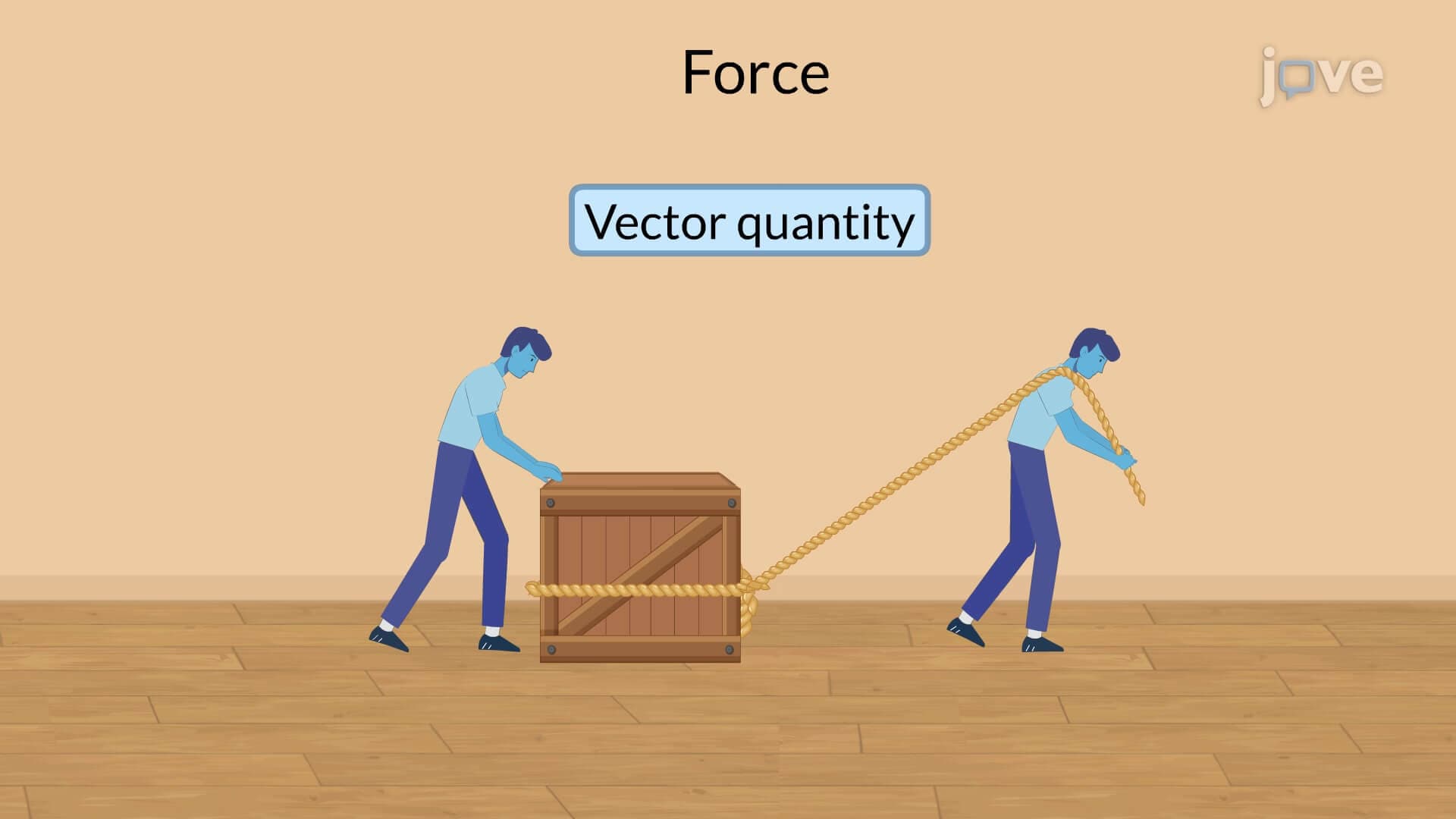
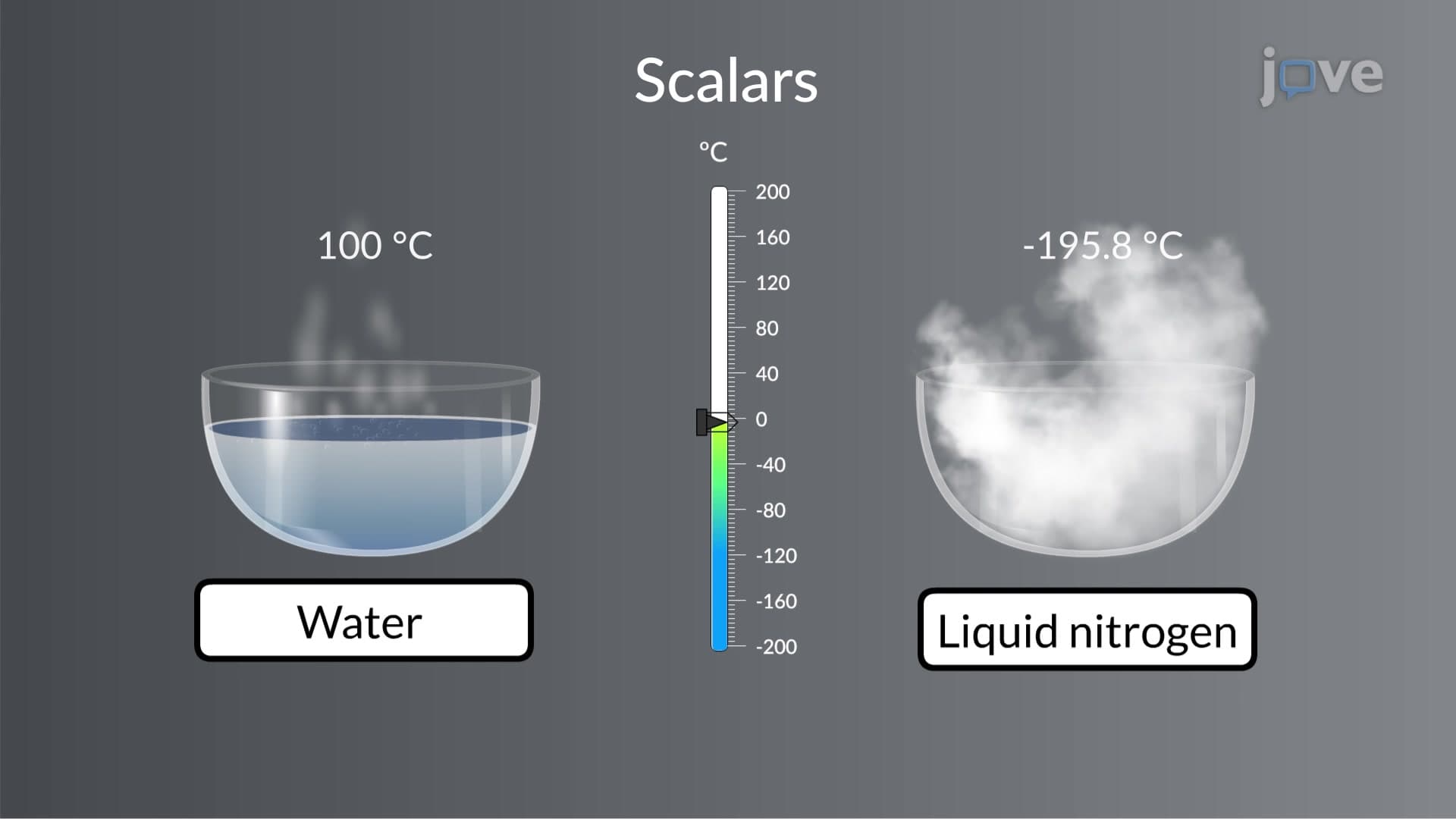
1. Scalar vs Vector Quantities in Force Analysis Understanding the distinction between scalars (magnitude only) and vectors (magnitude and direction) forms the foundation for force analysis. While mass and distance are scalar quantities, forces like weight and tension are vectors requiring both magnitude and directional specification. Consider a construction crane lifting materials-the crane's dimensions represent scalar properties, but the lifting force and cable tension are vector quantities with specific directions. This fundamental concept applies to all engineering systems from bridge design to aerospace applications, where precise force direction determines structural integrity and safety factors.
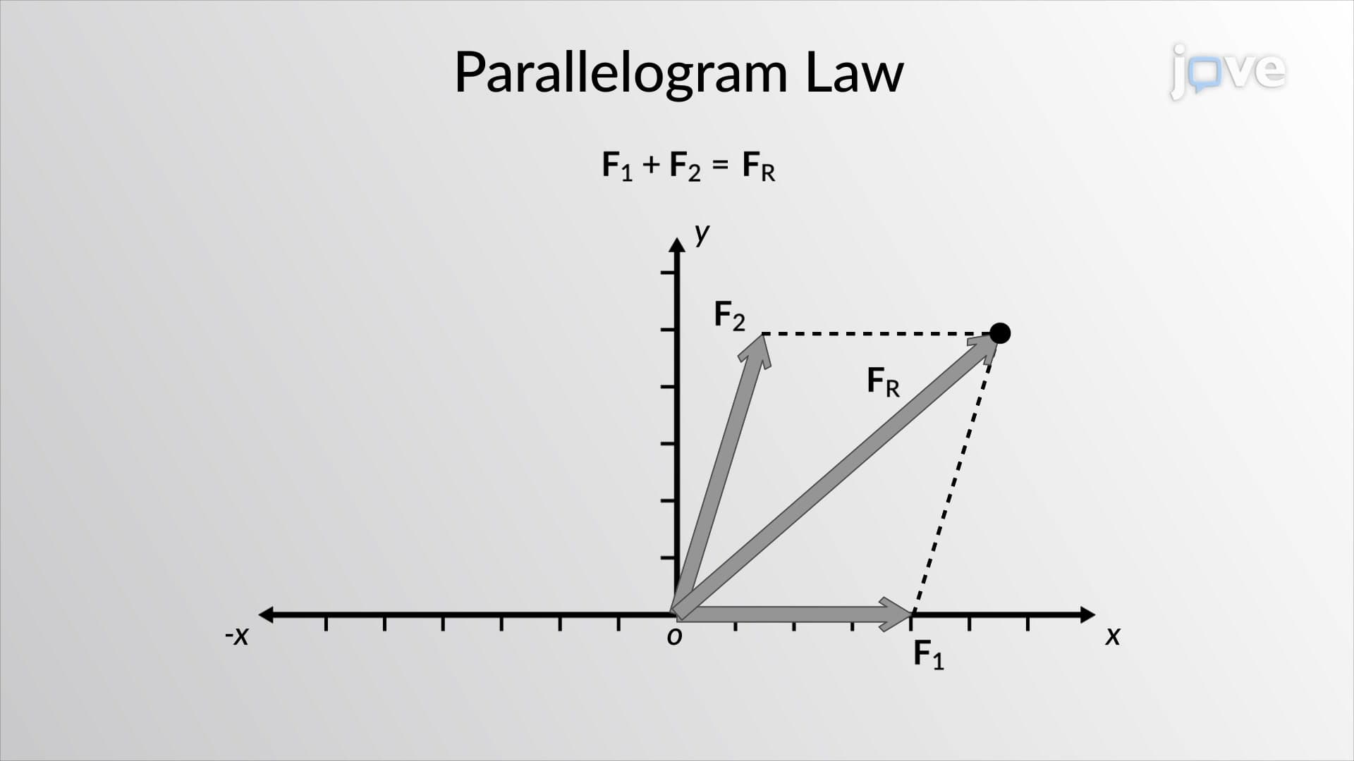
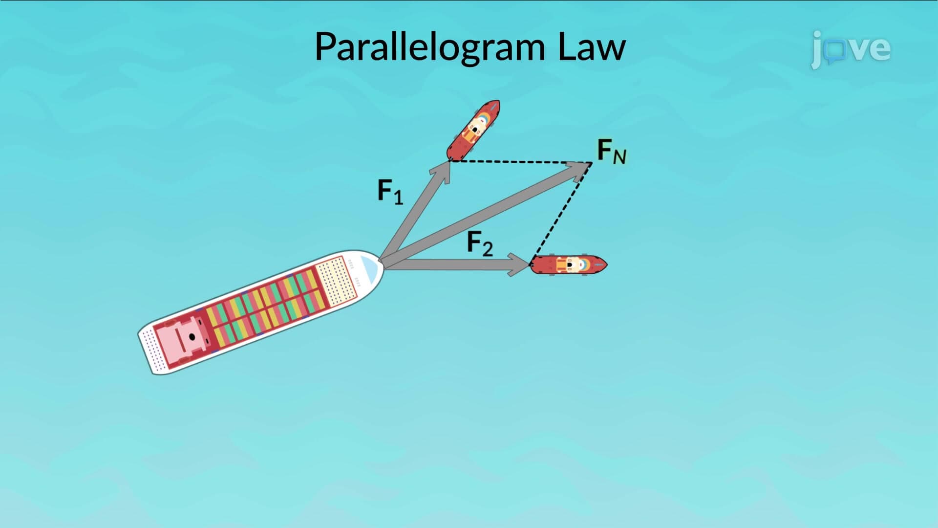
2. Vector Addition Methods and Parallelogram Law The parallelogram law provides the geometric foundation for combining multiple forces acting on a single point. When tugboats pull a ship from different directions, engineers use this method to determine the net force by drawing parallel lines to each force vector, creating a parallelogram whose diagonal represents the resultant force. The triangle rule offers an alternative approach, arranging vectors head-to-tail to find the same resultant. These methods prove essential in structural engineering, where multiple loads act simultaneously on building components, requiring accurate force combination calculations.
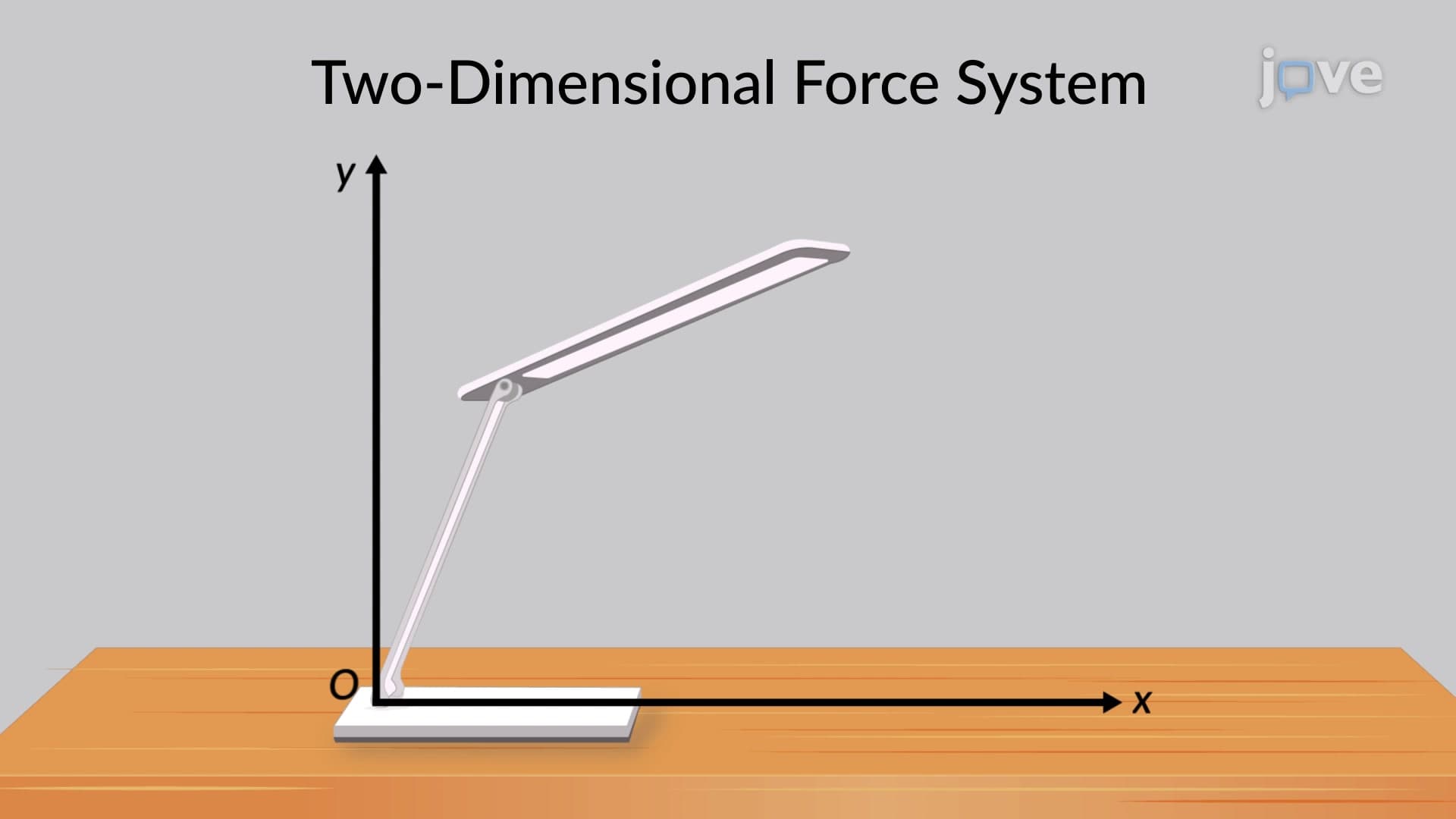
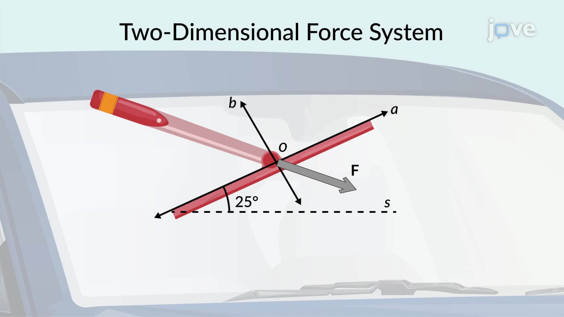
3. Two-Dimensional Force Systems and Components Breaking down forces into perpendicular components simplifies complex force analysis in planar systems. Consider a worker pulling a rope at an angle to move heavy equipment-the force resolves into horizontal and vertical components using trigonometric functions. The horizontal component produces motion while the vertical component affects normal forces. This resolution technique applies extensively in mechanical systems, from inclined plane problems in physics courses to analyzing forces in automotive suspension systems and construction equipment operations.
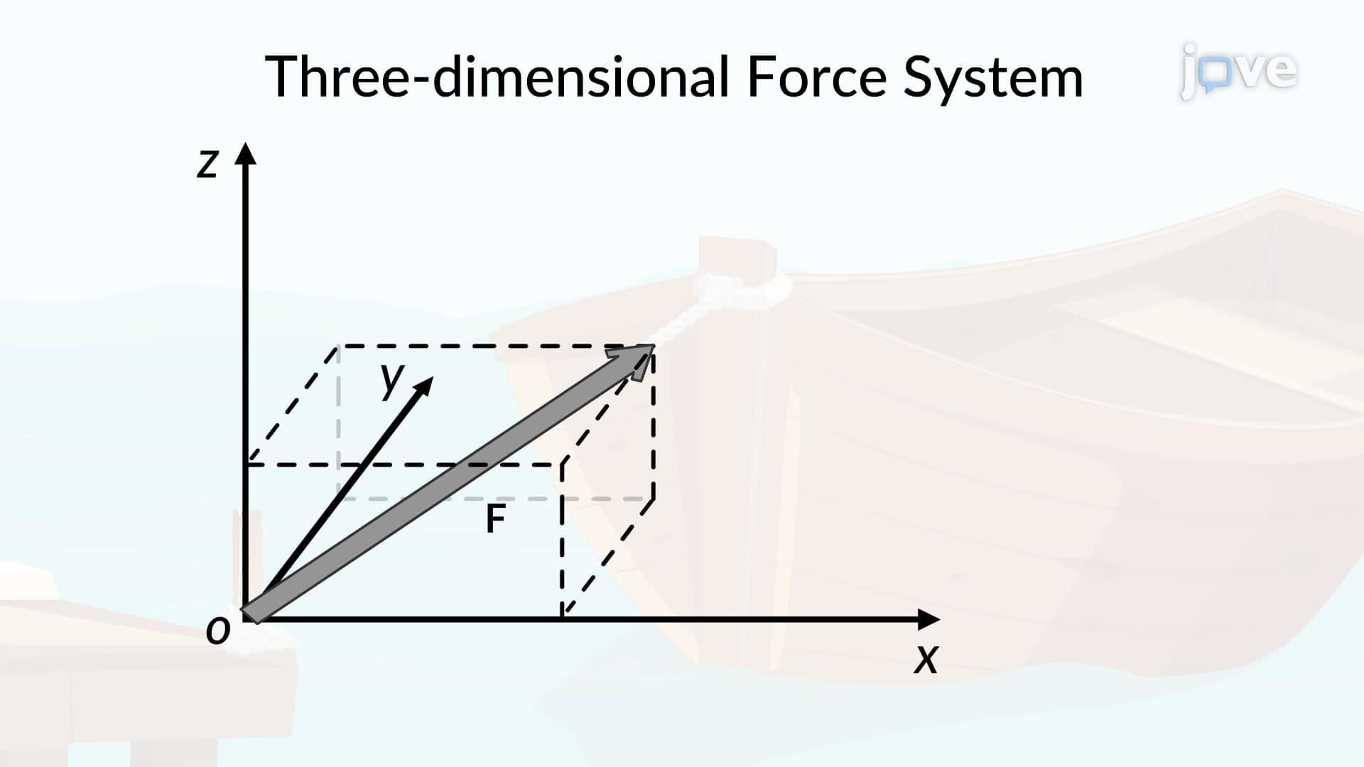
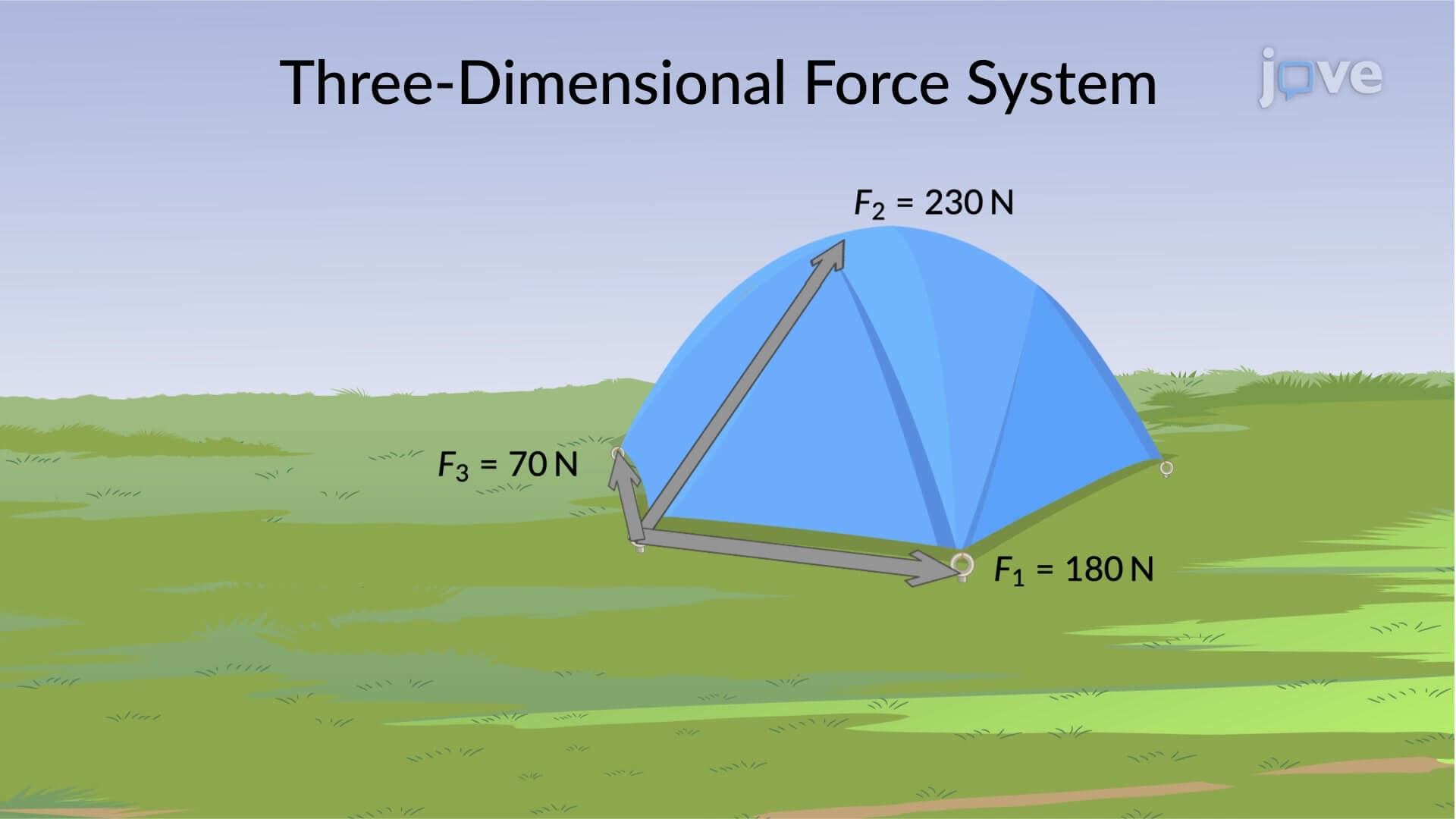
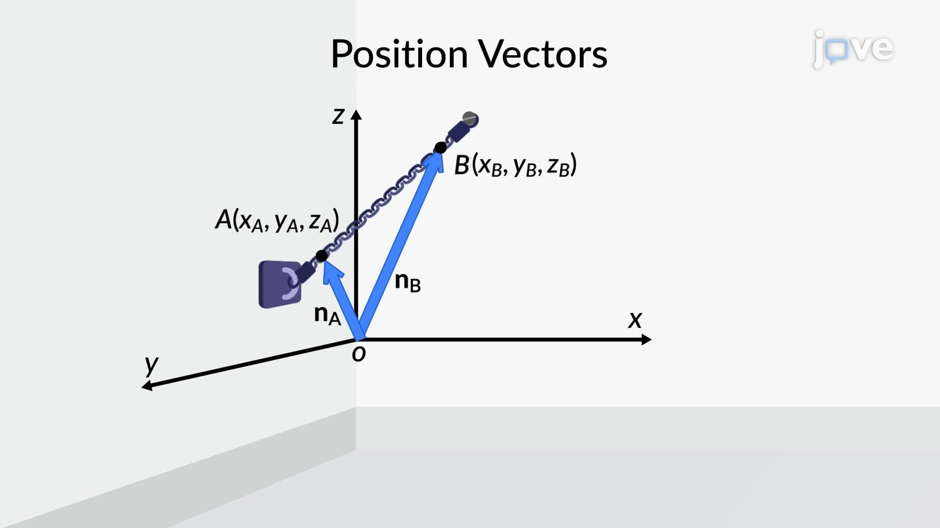
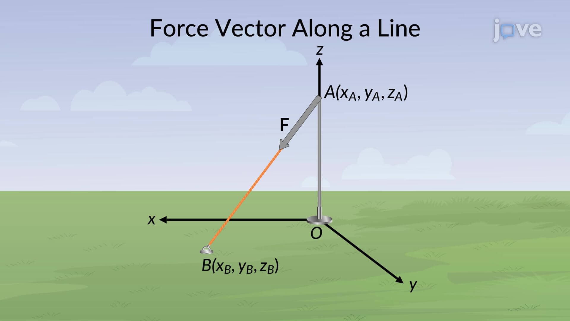
4. Cartesian Vector Notation and Unit Vectors Expressing forces using unit vectors i, j, and k along coordinate axes provides a systematic mathematical approach to three-dimensional force analysis. A force vector F = 50i + 30j - 20k newtons clearly indicates 50N in the x-direction, 30N in the y-direction, and 20N in the negative z-direction. This notation simplifies vector arithmetic operations and proves invaluable in computer-aided engineering analysis. Structural engineers use this method when analyzing complex frameworks like stadium roofs or bridge trusses where forces act in all three spatial dimensions.
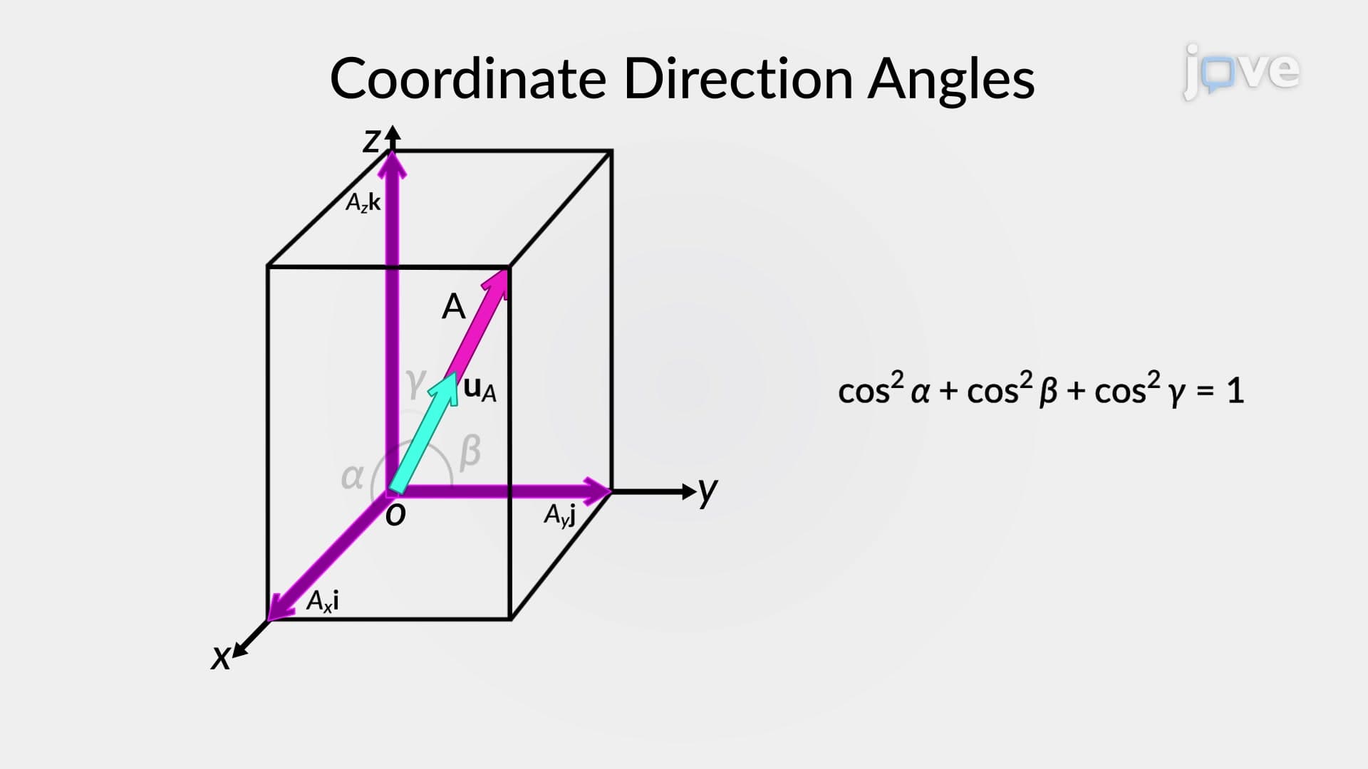
5. Direction Cosines and Three-Dimensional Force Orientation Direction cosines define a force vector's orientation in three-dimensional space using angles measured from coordinate axes. These cosines satisfy the fundamental relationship cos²α + cos²β + cos²γ = 1, providing a consistency check for calculations. Consider analyzing forces in a space frame structure-knowing two direction angles allows calculation of the third, ensuring accurate force representation. This concept proves crucial in aerospace engineering, robotics, and any application where precise spatial force orientation determines system performance and safety requirements.
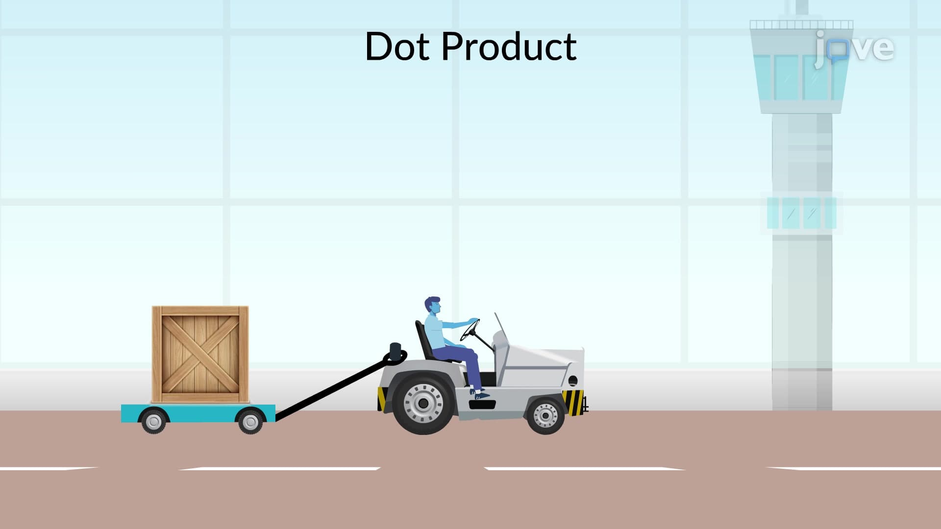
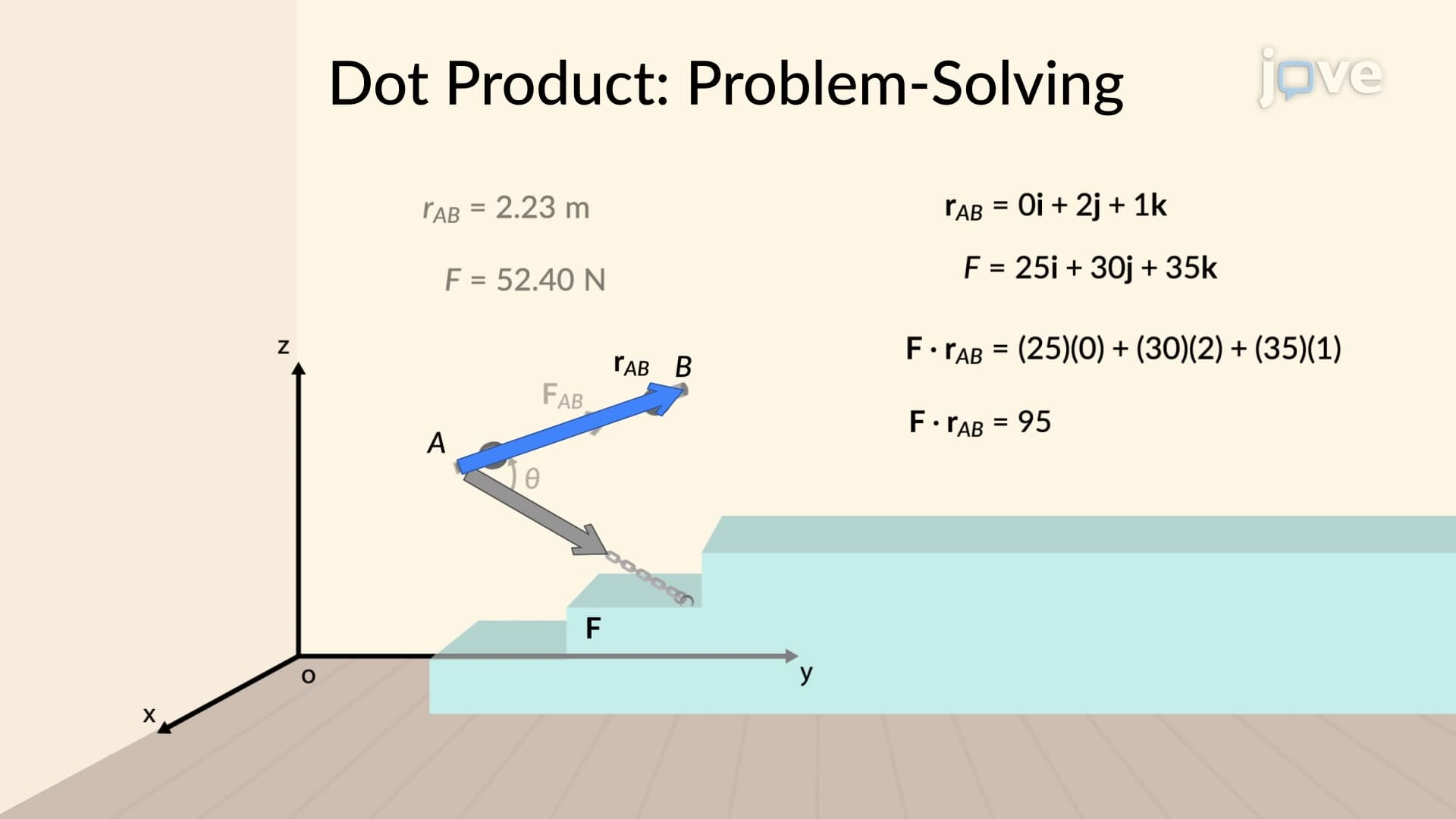
6. Vector Operations: Dot Product Applications The dot product operation calculates work done by forces, determines angles between force vectors, and finds force components along specific directions. When a forklift moves cargo horizontally while applying force at an angle, the work done equals the dot product of force and displacement vectors. This operation also determines whether forces are perpendicular (dot product = 0) or parallel (maximum dot product). Mechanical engineers use dot products extensively in power calculations, analyzing machine efficiency, and determining optimal force application angles in mechanical systems.
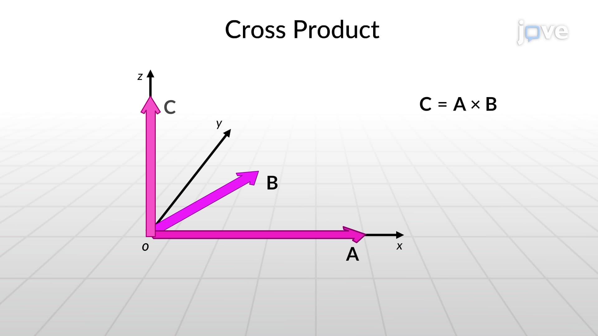
7. Cross Product and Perpendicular Force Relationships Cross products generate vectors perpendicular to two given vectors, essential for calculating moments and torques in mechanical systems. The right-hand rule determines the resulting vector's direction, while the magnitude equals the area of the parallelogram formed by the original vectors. Consider analyzing the torque produced by a wrench-the cross product of the force vector and position vector from the bolt center gives the moment vector. This operation proves fundamental in rotational mechanics, motor design, and any system involving rotational motion or moments about axes.