Loading video…


 7 Concepts
 1.9K views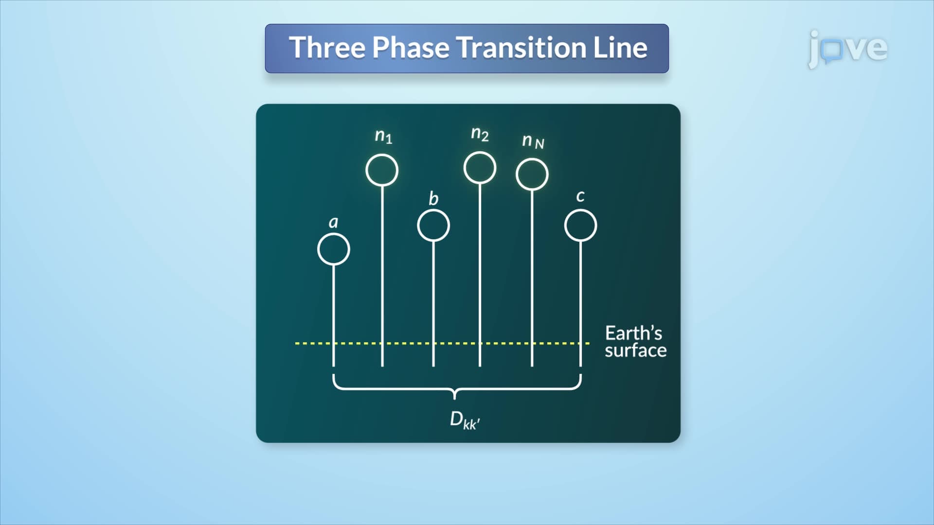

Video Summary: Series Impedances Three Phase Line Explained
Ever wonder why power grids across the US never fail completely during storms? The secret lies in understanding capacitance single phase and three phase systems and their impedance characteristics. When analyzing Series Impedances Three Phase Line Explained principles, engineers at utilities like Con Edison use sophisticated calculations involving neutral conductors and earth return paths to ensure stable power delivery. These same impedance concepts determine how electricity flows from power plants to your home. Watch the full video on JoVE Coach to master this concept with expert-led visuals and step-by-step explanations.
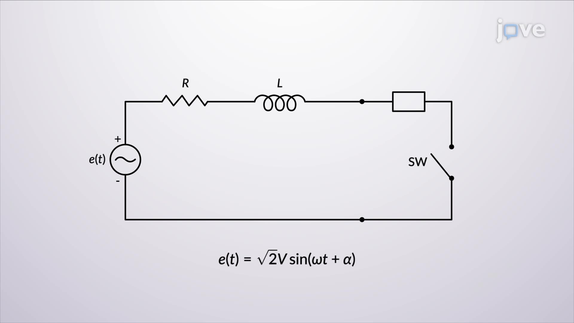
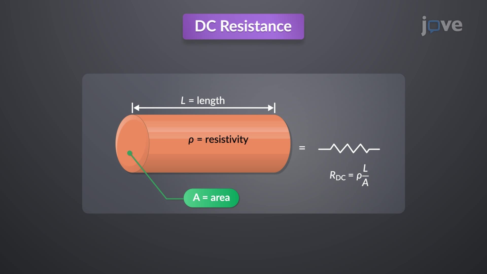
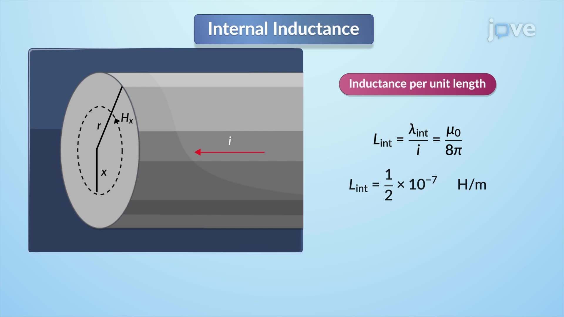
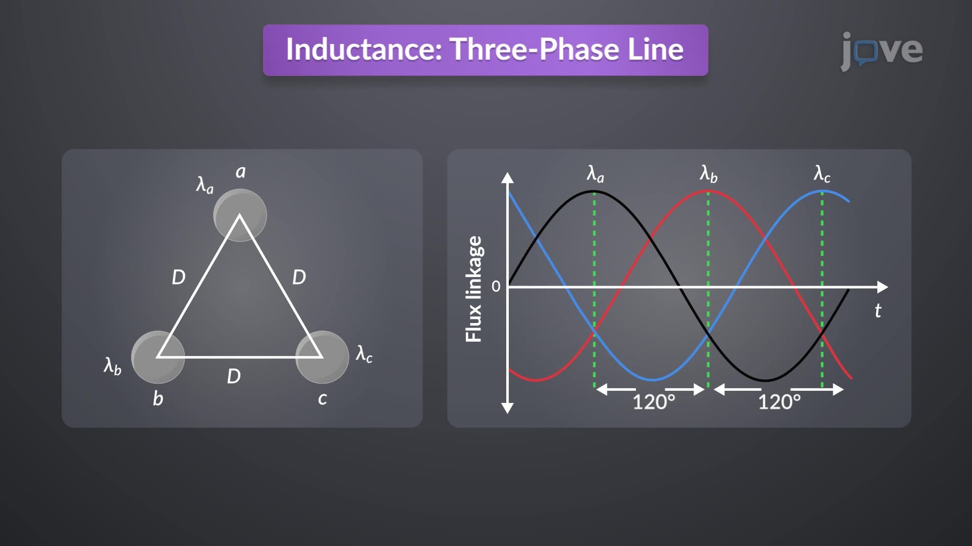
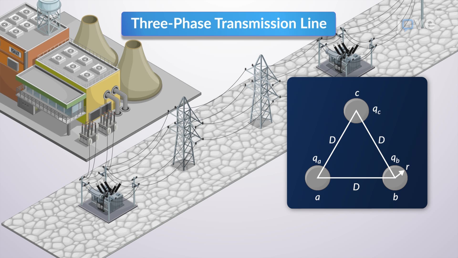
Series impedances in three-phase transmission lines represent the opposition to current flow through resistive and inductive components. Unlike simple single-phase circuits, three-phase systems require complex analysis because each phase conductor influences the others through electromagnetic coupling. This capacitance single phase and three phase interaction creates a network where current in one phase affects voltage drops in all phases.
Three-phase overhead lines typically include neutral conductors that provide return paths for unbalanced currents. When phase currents become unbalanced-common during fault conditions or asymmetric loads-return currents flow through neutral wires and earth connections, following paths of least impedance. How capacitance single phase and three phase systems handle these return currents determines overall system stability.
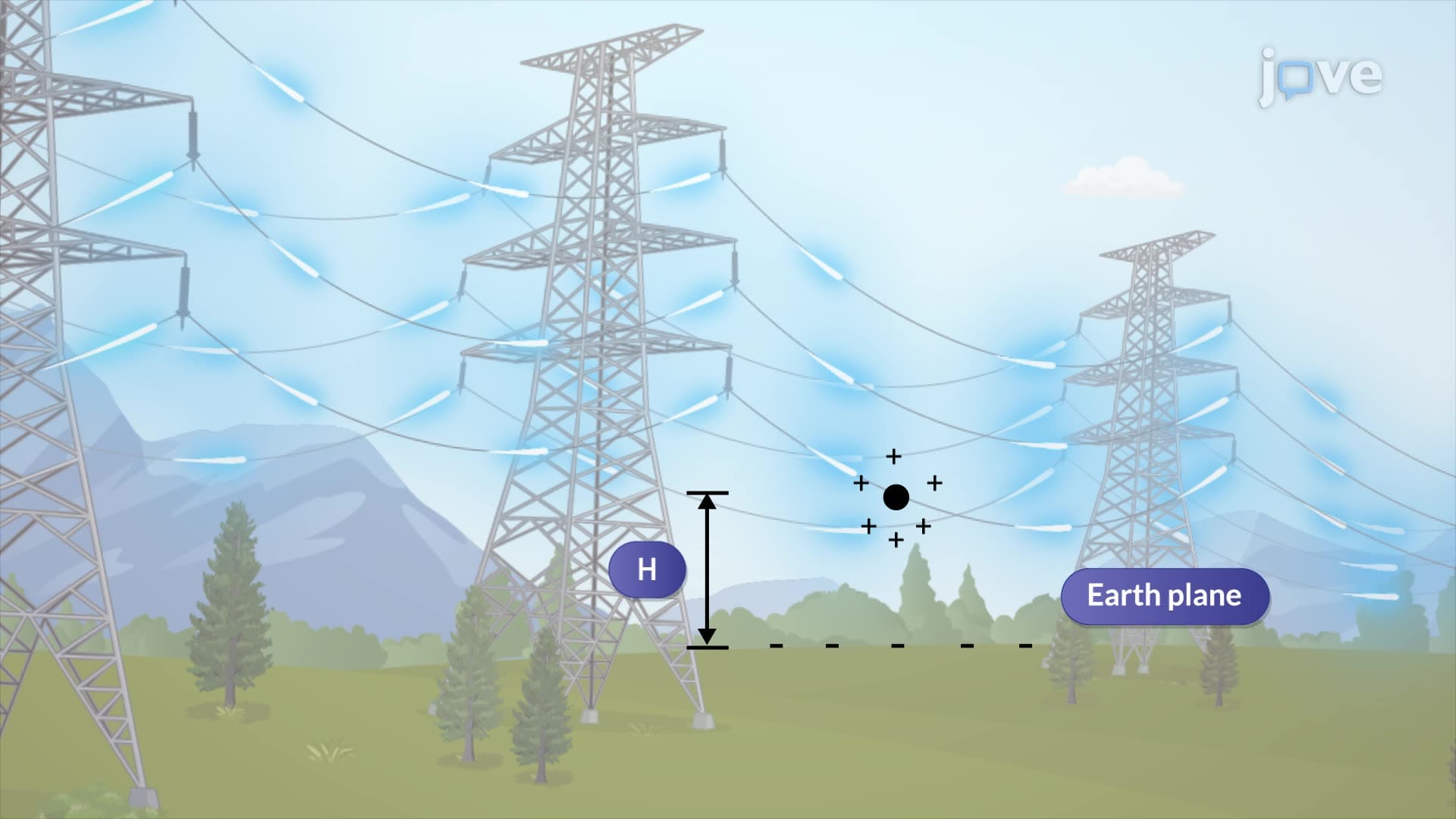
Engineers model earth return using equivalent conductors with identical geometric mean radius and resistance to their overhead counterparts. This mathematical substitution simplifies complex electromagnetic field calculations while maintaining accuracy for practical applications in utilities like Pacific Gas & Electric or Duke Energy.
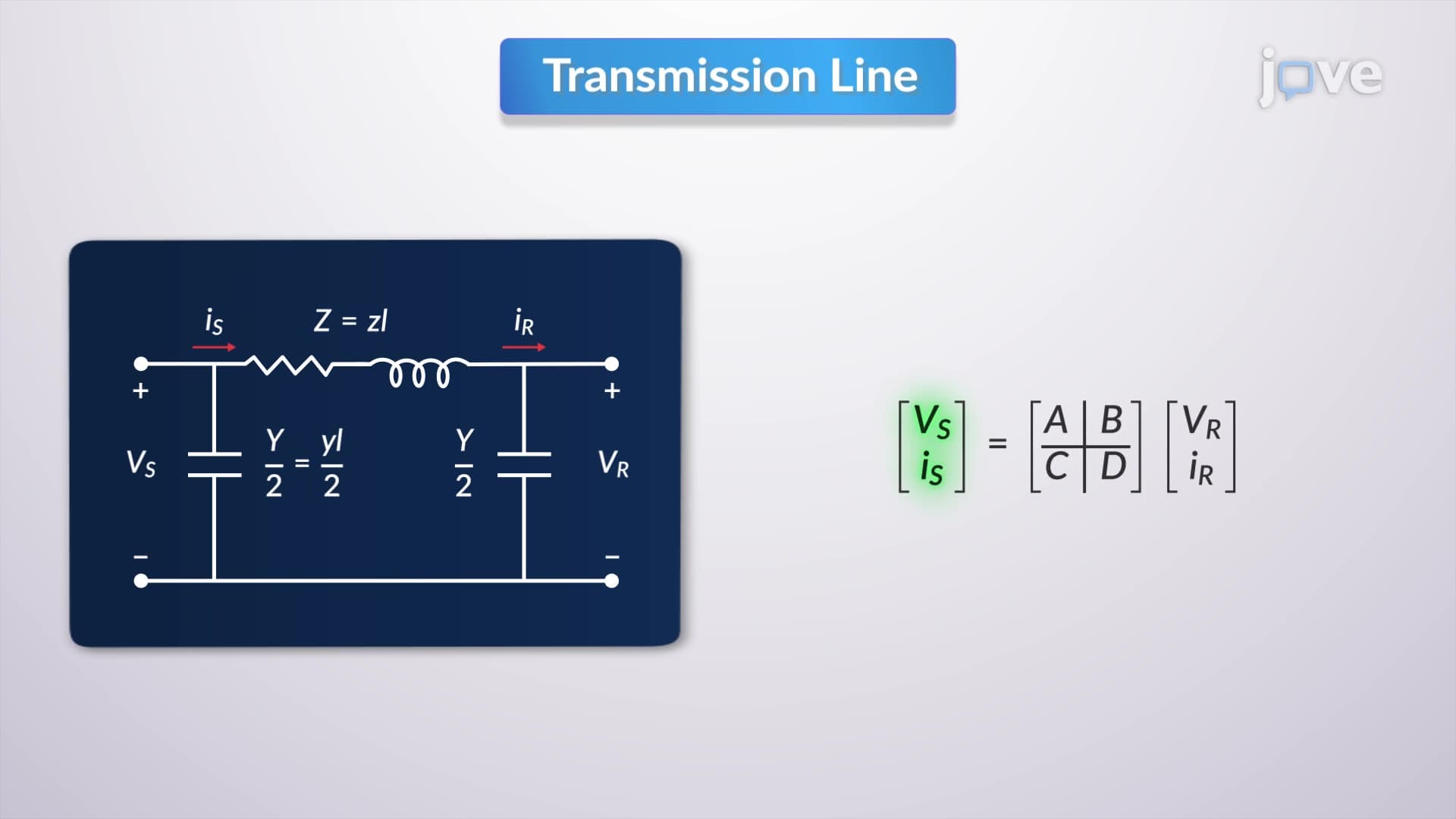
The three-by-three series-phase impedance matrix serves as the cornerstone for analyzing three-phase line behavior. Each element represents mutual impedance between phase conductors, creating a comprehensive picture of electromagnetic interactions. Students preparing for AP Physics or college-level electrical engineering courses encounter these matrices when studying power systems.
For fully transposed lines-where conductors systematically exchange positions-engineers average diagonal and off-diagonal matrix elements. This averaging technique provides generalized line behavior suitable for steady-state analysis used in power flow studies conducted by regional transmission organizations like ERCOT or PJM Interconnection.
Understanding capacitance single phase and three phase impedance calculations proves essential for power system engineers designing transmission infrastructure. The Federal Energy Regulatory Commission (FERC) requires utilities to demonstrate impedance calculations for new transmission projects. Students studying for the Fundamentals of Engineering (FE) exam or pursuing Professional Engineer (PE) licensure must master these concepts.
Real-world applications include fault analysis, protective relay coordination, and voltage regulation studies. When Hurricane Sandy damaged transmission lines in 2012, utilities used impedance calculations to reroute power through alternate paths, demonstrating the critical importance of these mathematical models in maintaining grid reliability.
Related Micro-courses