13 Concepts
11 Concepts
9 Concepts
8 Concepts
13 Concepts
16 Concepts
9 Concepts
11 Concepts
15 Concepts
11 Concepts
14 Concepts
20 Concepts
11 Concepts
7 Concepts
5 Concepts
7 Concepts
10 Concepts
7 Concepts
7 Concepts
5 Concepts
9 Concepts
7 Concepts
7 Concepts
7 Concepts
10 Concepts
4 Concepts
7 Concepts
6 Concepts
8 Concepts
9 Concepts
7 Concepts
5 Concepts
5 Concepts
Steady-state transmission lines and power flows form the backbone of electrical grid analysis across the United States. This comprehensive course explores transmission line modeling using differential equations, ABCD parameters, and equivalent circuits. Students will master load flow analysis techniques including Gauss-Seidel and Newton-Raphson methods, examine power flow control mechanisms, and apply fast decoupled algorithms used by utilities like PG&E and ConEd. JoVE Coach provides interactive problem-solving support throughout your learning journey.
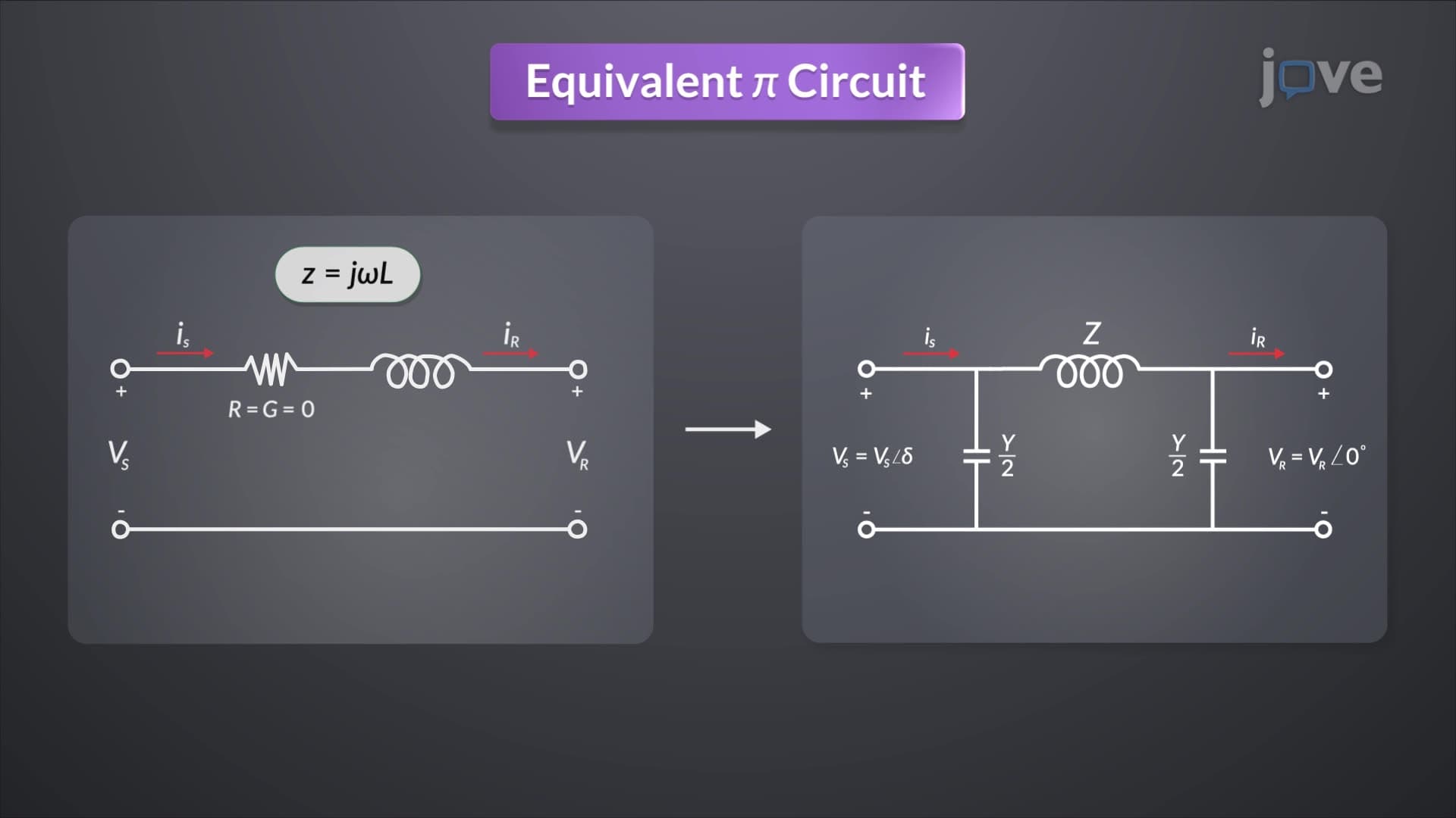
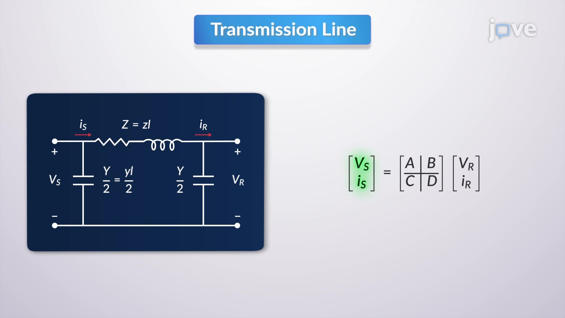
1. Transmission Line Differential Equations and ABCD Parameters Understanding how voltage and current vary along transmission lines requires solving differential equations derived from Kirchhoff's laws. The ABCD parameter matrix relates sending-end and receiving-end quantities, enabling analysis of any line length. These parameters incorporate the propagation constant (combining resistance, inductance, conductance, and capacitance per unit length) and characteristic impedance. For the 765 kV transmission lines connecting New York to Canadian hydroelectric plants, ABCD parameters help engineers calculate voltage drops and power losses across hundreds of miles.
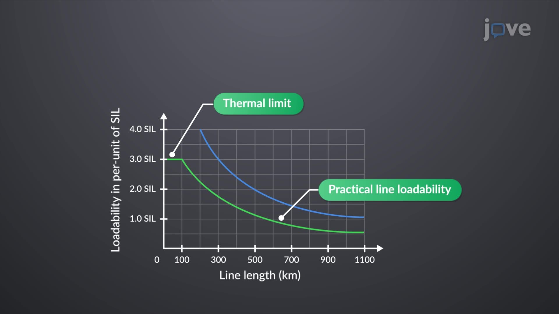
2. Lossless Lines and Surge Impedance Loading Lossless transmission lines, while idealized, provide essential insights into power system behavior. The surge impedance loading represents the natural power-carrying capability where voltage remains constant along the line. For a typical 345 kV line with 400-ohm surge impedance, this equals approximately 300 MW. Understanding wavelength concepts helps explain why 60 Hz power lines behave differently at various lengths - a critical consideration when utilities like Duke Energy plan new transmission corridors across the Carolinas.
3. Maximum Power Flow and Stability Limits Theoretical maximum power transfer occurs when the phase angle difference between sending and receiving ends reaches 90 degrees, but practical limits are much lower. The steady-state stability limit considers voltage drop constraints (typically 5% maximum) and angular displacement limits (30-35 degrees) to ensure reliable operation. California's grid operators use these principles when managing power transfers from desert solar farms to coastal load centers, maintaining system stability while maximizing renewable energy delivery.
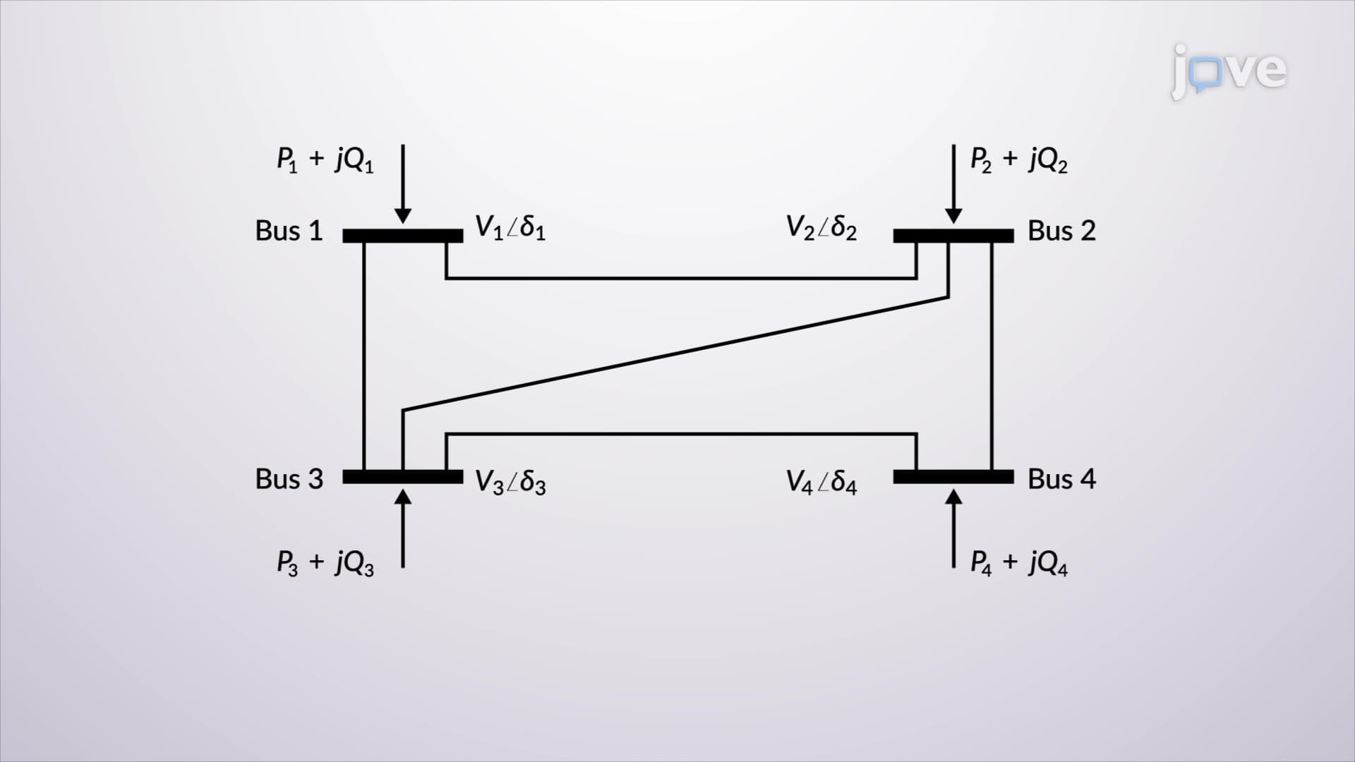
4. Power Flow Problem Formulation and Bus Classifications Power system analysis requires classifying network buses into three types: slack buses (voltage and angle specified), PV buses (real power and voltage specified), and PQ buses (real and reactive power specified). The bus admittance matrix, constructed from transmission line impedances and shunt elements, forms the foundation for nodal analysis. When analyzing the Texas grid (ERCOT), engineers must account for hundreds of buses representing generation plants, substations, and major load centers throughout the state.
5. Load Flow Solution Methods: Gauss-Seidel and Newton-Raphson Solving the nonlinear power flow equations requires iterative numerical methods. The Gauss-Seidel method offers simplicity but slower convergence, while Newton-Raphson provides faster, more robust solutions using the Jacobian matrix. These algorithms determine voltage magnitudes and phase angles at each bus, enabling calculation of line flows and losses. ISO New England uses advanced versions of these methods to perform thousands of power flow studies annually, ensuring grid reliability during peak summer demand periods.
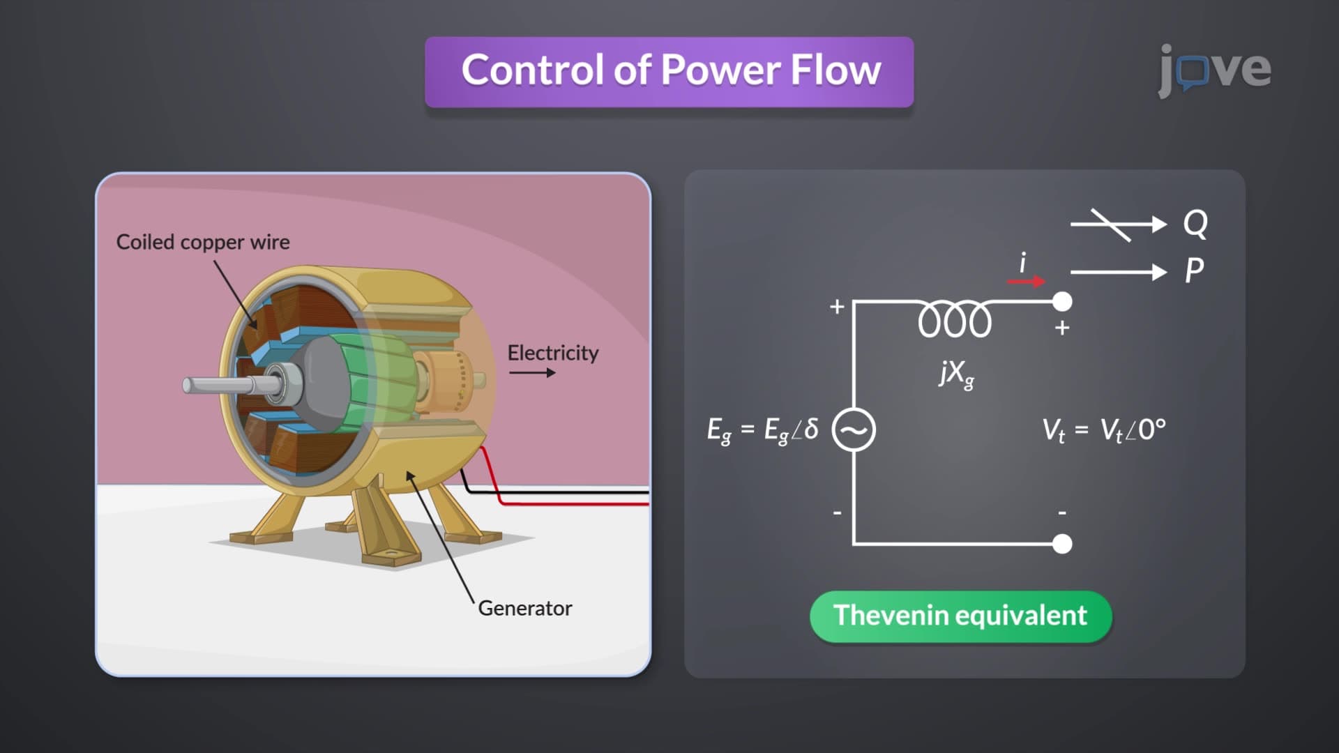
6. Power Flow Control Devices and Methods Controlling power flows requires coordinating multiple devices: generators adjust real and reactive power output through prime mover and excitation control, shunt capacitor banks and reactors provide voltage support, and regulating transformers control both voltage levels and phase angles. Static VAR compensators offer dynamic reactive power control. When managing power flows on the Pacific DC Intertie connecting Oregon to California, operators coordinate these control devices to maintain optimal power transfer while preserving system stability.
7. Fast Decoupled and DC Power Flow Analysis Real-time power system operations demand rapid analysis capabilities. Fast decoupled power flow exploits the weak coupling between real power-voltage angle and reactive power-voltage magnitude relationships, simplifying the Jacobian matrix structure. DC power flow further simplifies analysis by assuming constant voltage magnitudes and focusing solely on real power flows. The Midwest ISO uses these techniques for security assessment, quickly evaluating hundreds of contingency scenarios to ensure grid reliability across thirteen states.