13 Concepts
11 Concepts
9 Concepts
8 Concepts
13 Concepts
16 Concepts
9 Concepts
11 Concepts
15 Concepts
11 Concepts
14 Concepts
20 Concepts
11 Concepts
7 Concepts
5 Concepts
7 Concepts
10 Concepts
7 Concepts
7 Concepts
5 Concepts
9 Concepts
7 Concepts
7 Concepts
7 Concepts
10 Concepts
4 Concepts
7 Concepts
6 Concepts
8 Concepts
9 Concepts
7 Concepts
5 Concepts
5 Concepts
Diodes are fundamental semiconductor devices that control current flow in electronic circuits. From simple p-n junction structures to specialized Zener and Schottky variants, these components enable essential functions like rectification, voltage regulation, and signal processing. Understanding diode characteristics circuits and operation and applications of diodes is crucial for students pursuing electrical engineering careers in the US technology sector, where diodes power everything from smartphone chargers to industrial equipment. JoVE Coach makes these complex concepts accessible through practical circuit analysis.
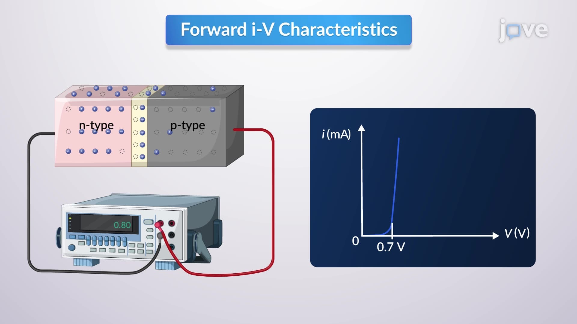
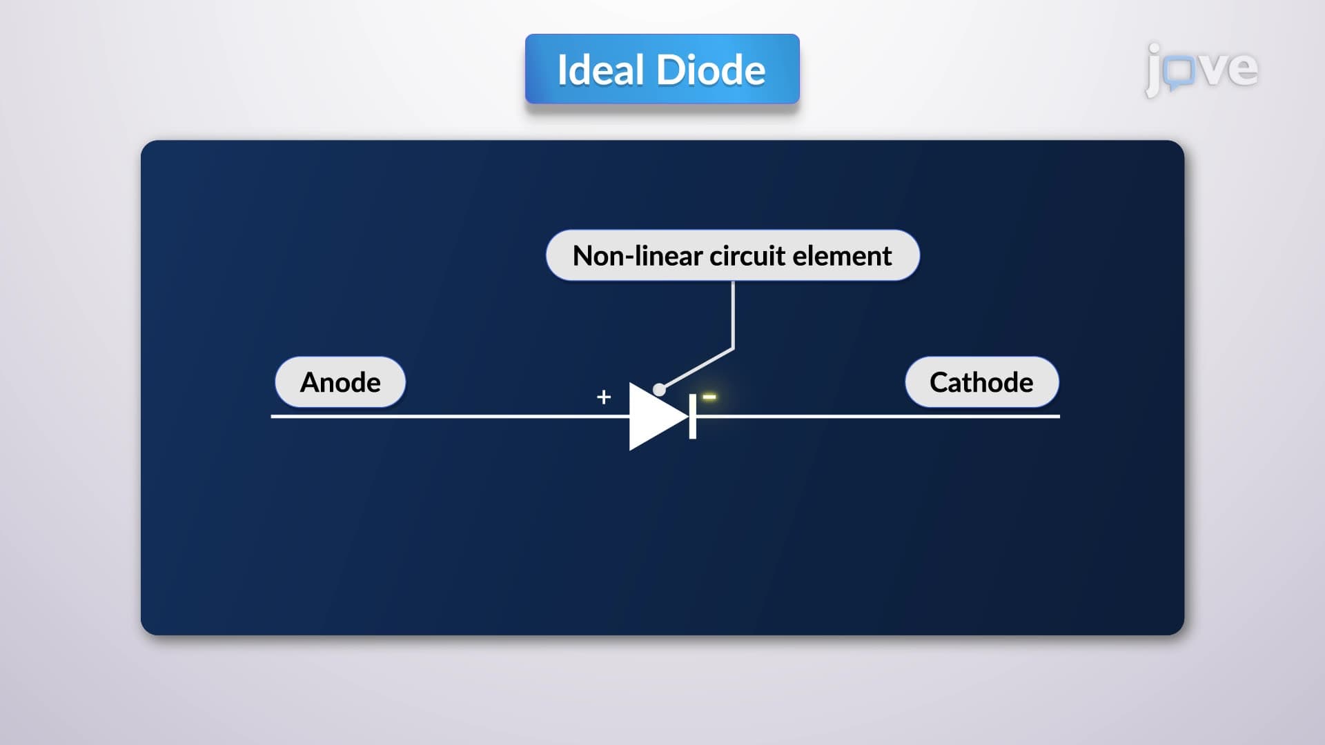
1. Ideal vs. Practical Diode Behavior and P-N Junction Physics Understanding how diodes function starts with the p-n junction, where p-type and n-type semiconductor materials meet. Ideal diodes act as perfect one-way valves-conducting with zero resistance in forward bias and blocking all current in reverse bias. However, practical diodes exhibit a forward voltage drop (typically 0.7V for silicon diodes) and small leakage currents in reverse bias. The diode curve shows this relationship graphically, with negligible current below the cut-in voltage, then exponential current increase. This behavior enables applications in US power grids, where diodes protect sensitive equipment from reverse voltage damage.
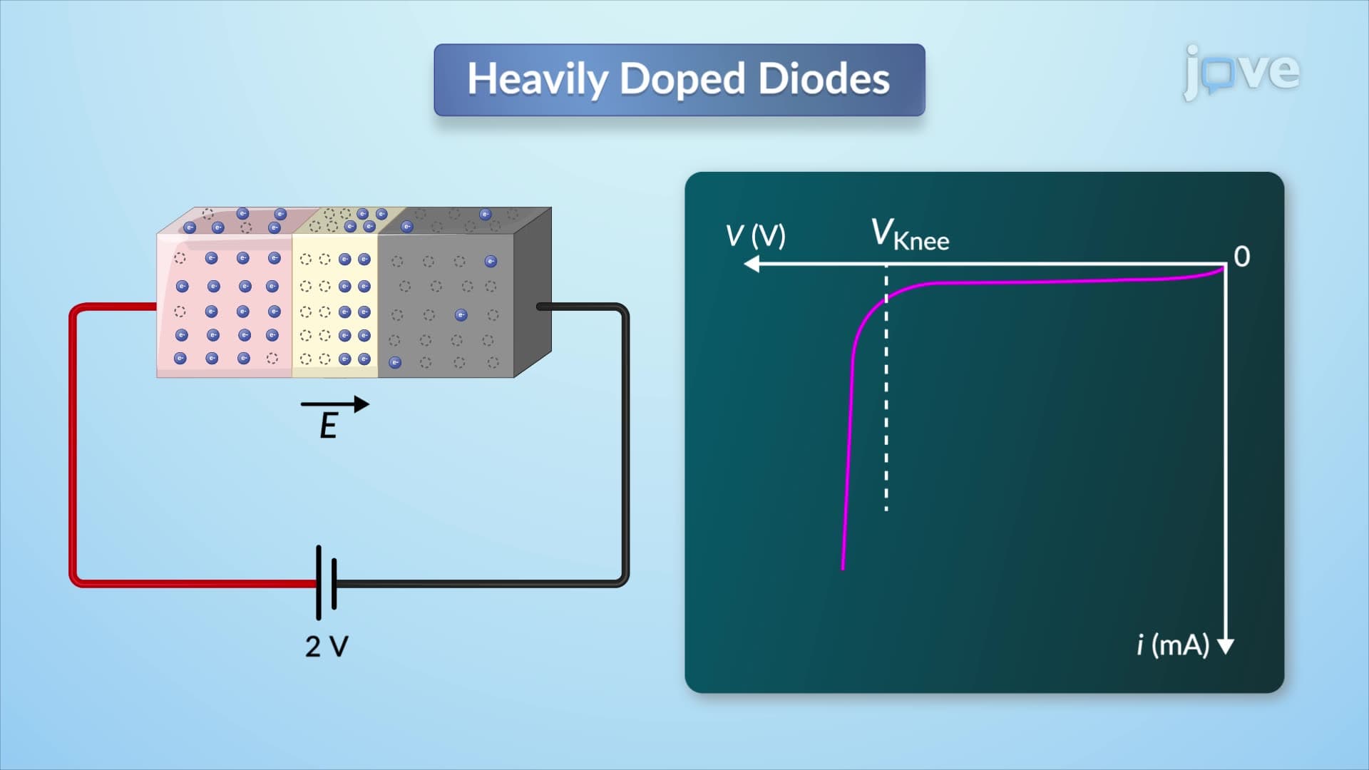
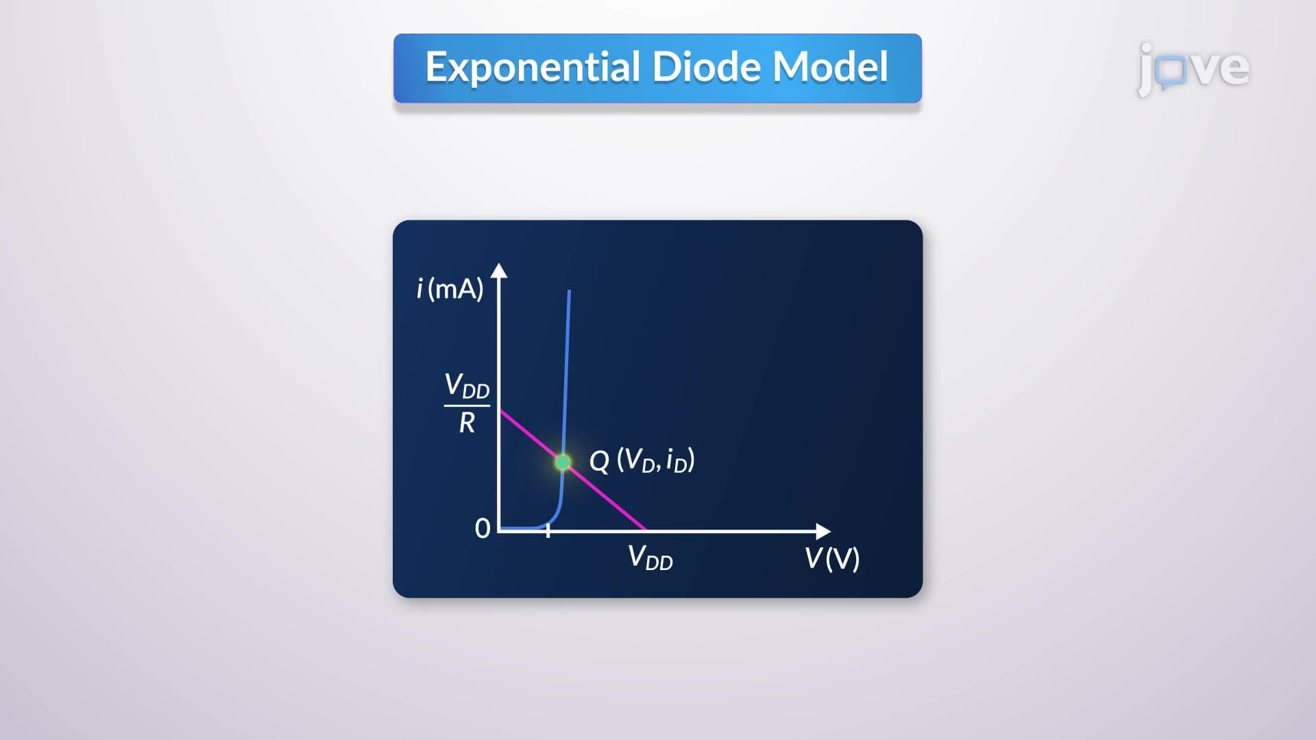
2. Forward and Reverse Bias Characteristics in Circuit Applications Forward bias occurs when the p-region connects to positive voltage and n-region to negative, allowing current flow once the barrier voltage is overcome. The current-voltage relationship follows an exponential law involving thermal voltage and saturation current. Reverse bias creates the opposite connection, blocking current until breakdown voltage is reached. These characteristics determine diode selection for US telecommunications infrastructure, where forward voltage drop affects power efficiency in cellular tower amplifiers, and reverse breakdown ratings protect against lightning-induced voltage spikes.
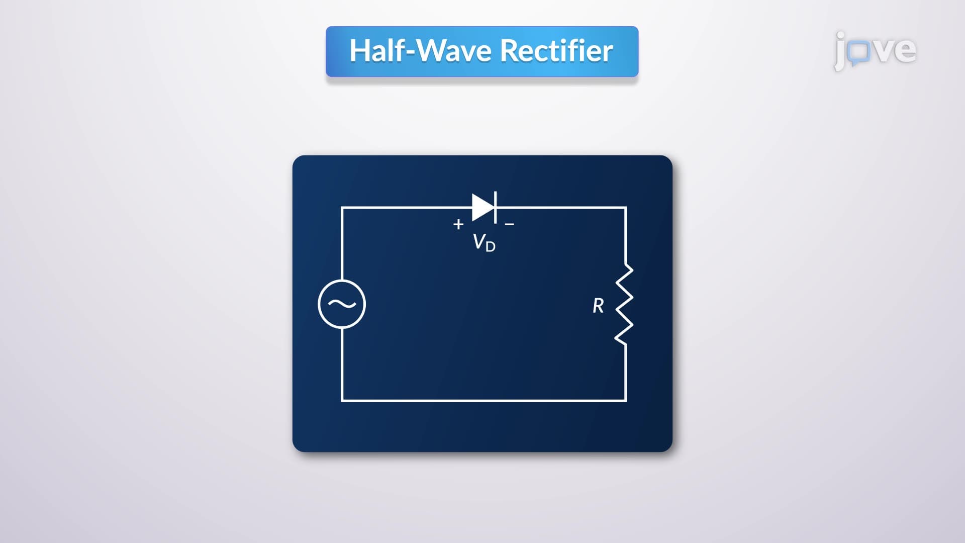
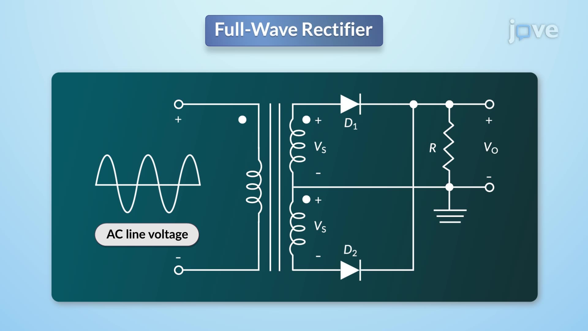
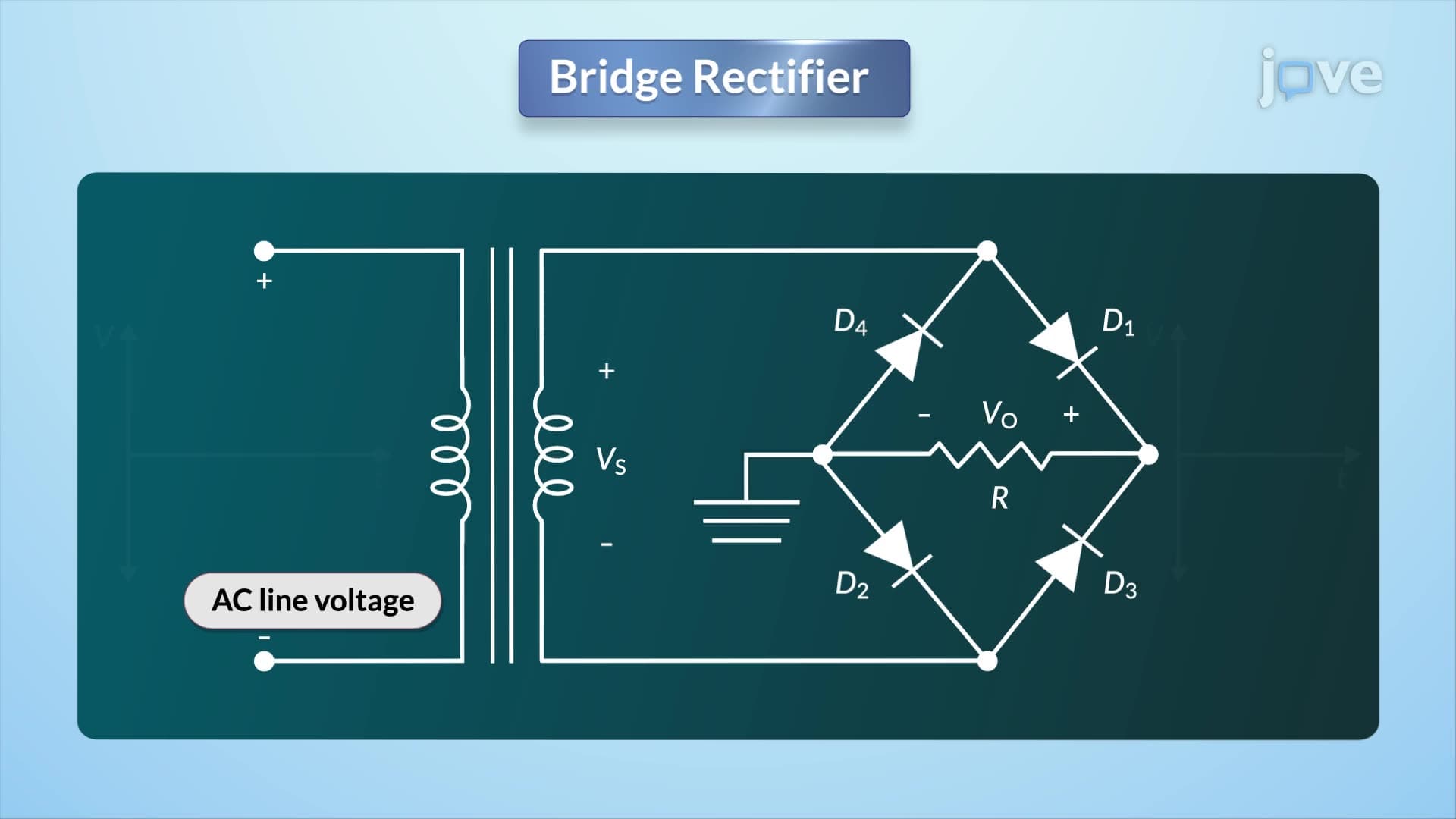
3. Rectifier Circuits for AC-to-DC Power Conversion Half-wave rectifiers use single diodes to convert AC to pulsating DC, conducting only during positive half-cycles while blocking negative portions. Full-wave rectifiers employ center-tapped transformers and two diodes for improved efficiency, rectifying both half-cycles. Bridge rectifiers use four diodes in a diamond configuration, eliminating transformer center-tap requirements. These circuits form the backbone of US consumer electronics-from laptop chargers converting 120V AC household power to low-voltage DC, to industrial motor drives in manufacturing facilities requiring precise DC control.
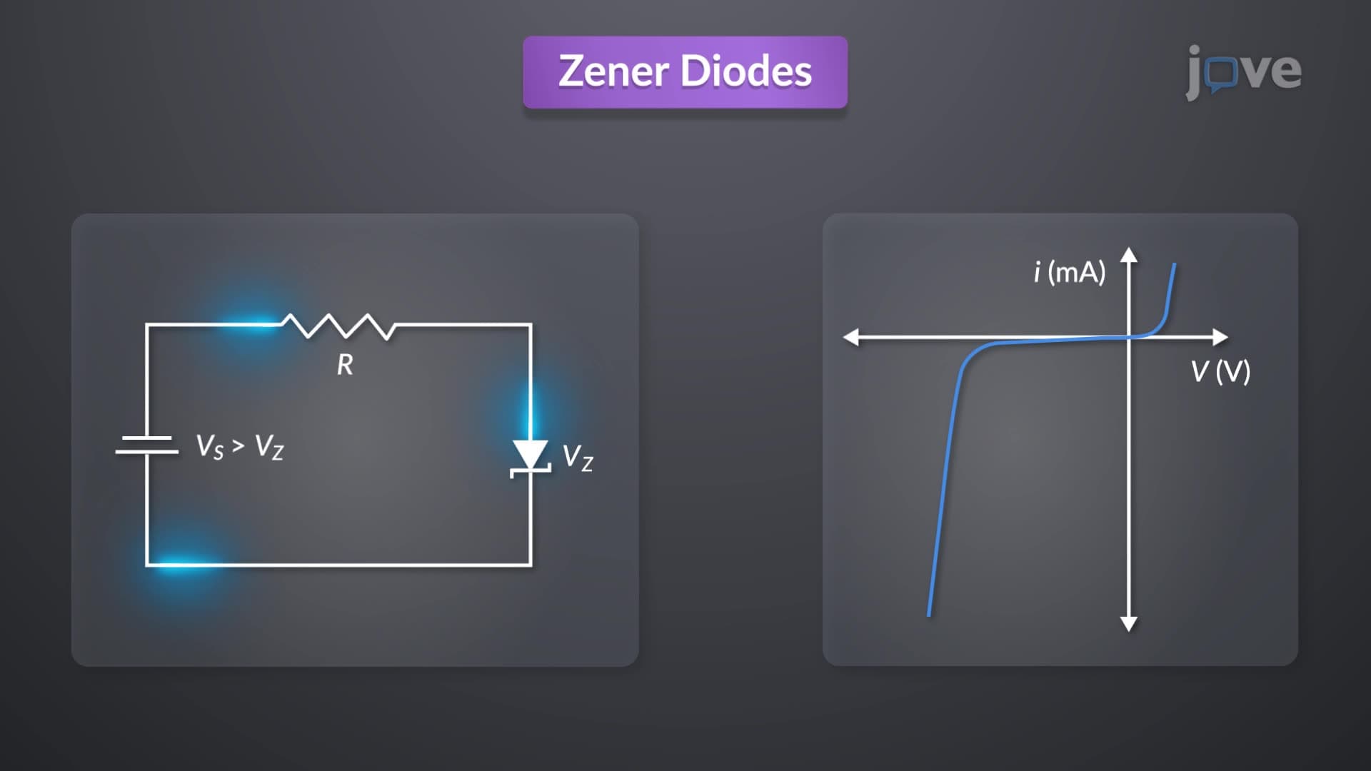
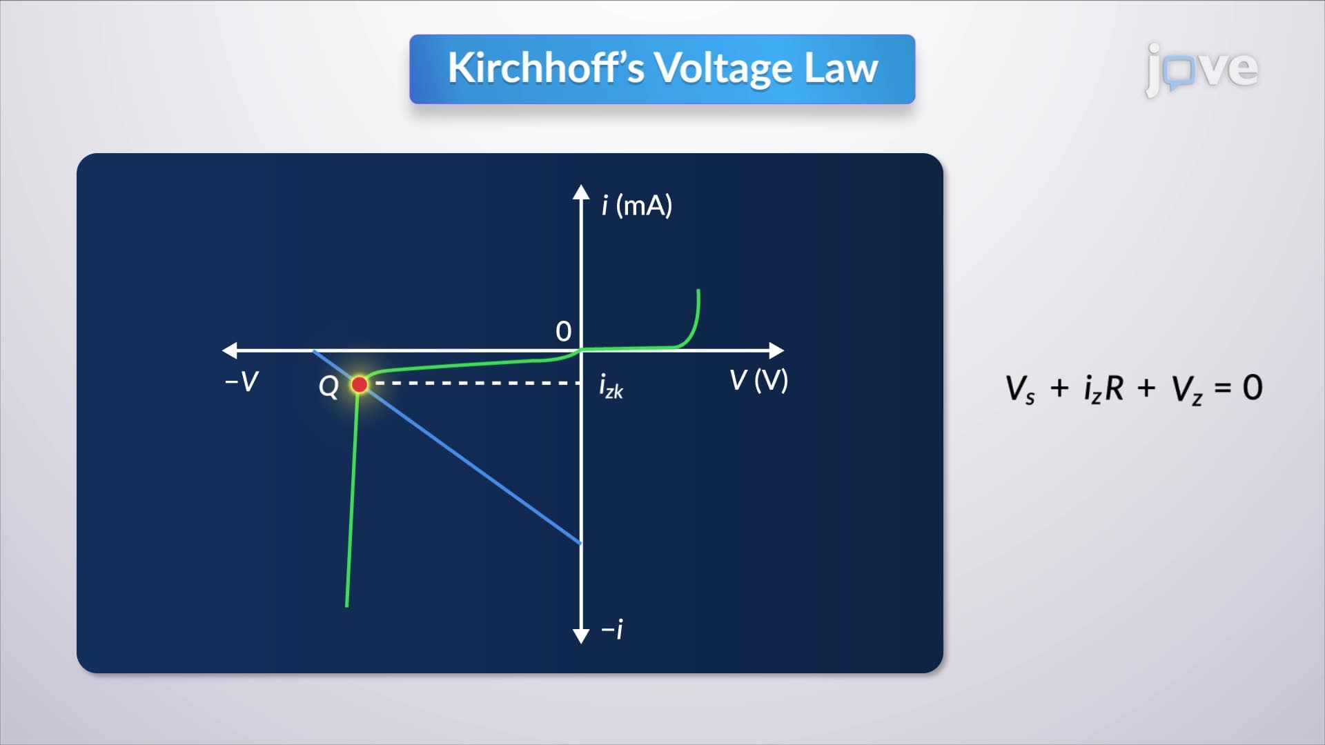
4. Zener Diodes and Voltage Regulation Principles Zener diodes operate in reverse breakdown mode to maintain constant voltage across varying current levels, making them ideal voltage regulators. Below the Zener voltage, they block current like regular diodes. Above this threshold, they conduct while maintaining nearly constant voltage drop. The sharp knee in the I-V curve indicates the transition to regulation mode. US automotive electronics rely heavily on Zener regulation-protecting 12V car computer systems from alternator voltage fluctuations, and maintaining stable reference voltages in engine control modules despite temperature variations.
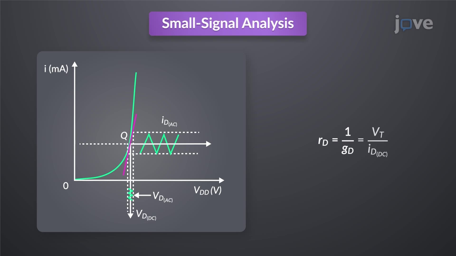
5. Small-Signal Modeling and High-Frequency Analysis Small-signal diode models simplify analysis when AC signals are superimposed on DC bias currents. The incremental resistance equals thermal voltage divided by bias current, allowing linear analysis of nonlinear diode circuits. This technique proves essential for RF applications common in US wireless communications, where diodes in cell phone receivers must handle both strong DC bias currents and weak AC signals simultaneously. The small-signal conductance determines how effectively the diode can demodulate high-frequency signals in radio receivers and radar systems.
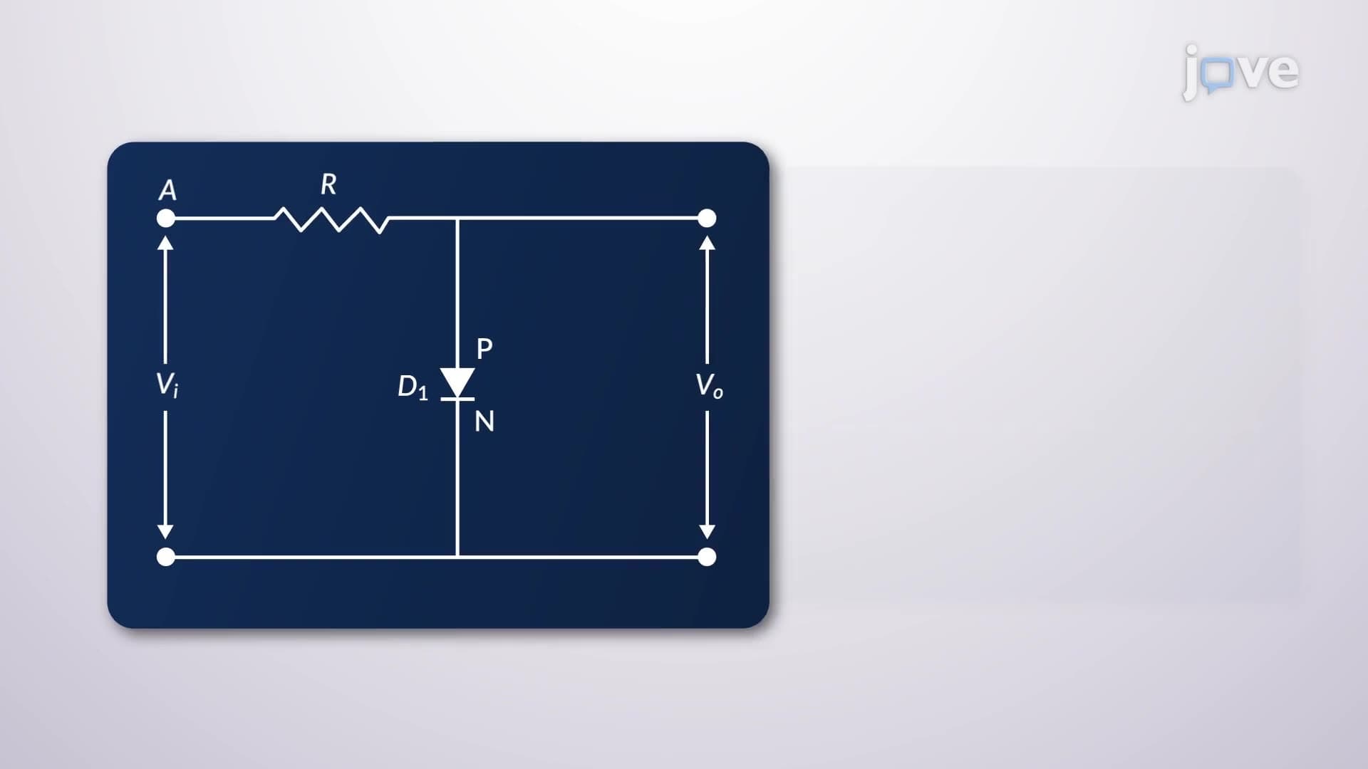
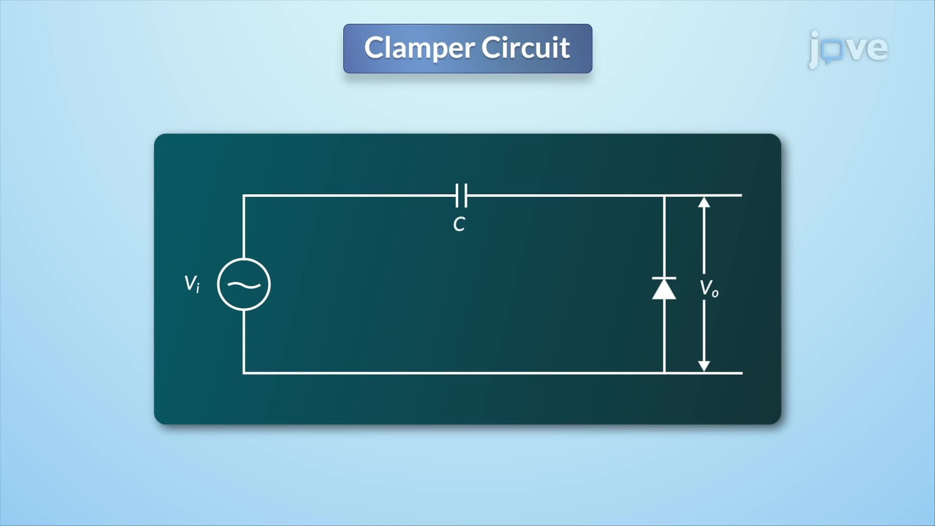
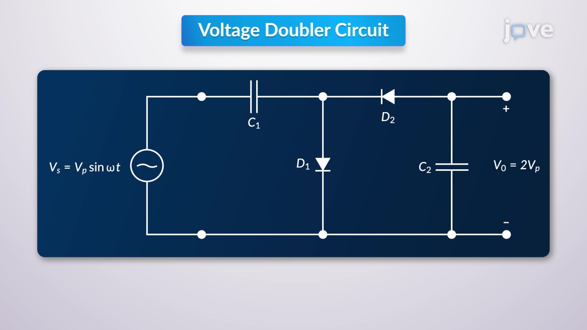
6. Wave-Shaping Circuits: Clippers, Clampers, and Voltage Doublers Clipper circuits use biased diodes to remove portions of input waveforms, protecting sensitive components from overvoltage. Clamper circuits shift DC levels without changing waveform shape, using capacitor-diode combinations for level restoration. Voltage doublers cascade clamping and rectification to generate output voltages twice the input amplitude. These circuits enable US broadcast television systems to maintain proper signal levels-clippers prevent transmitter overload, clampers restore DC components lost in AC-coupled circuits, and voltage doublers provide high voltages for cathode-ray tube displays in older equipment.
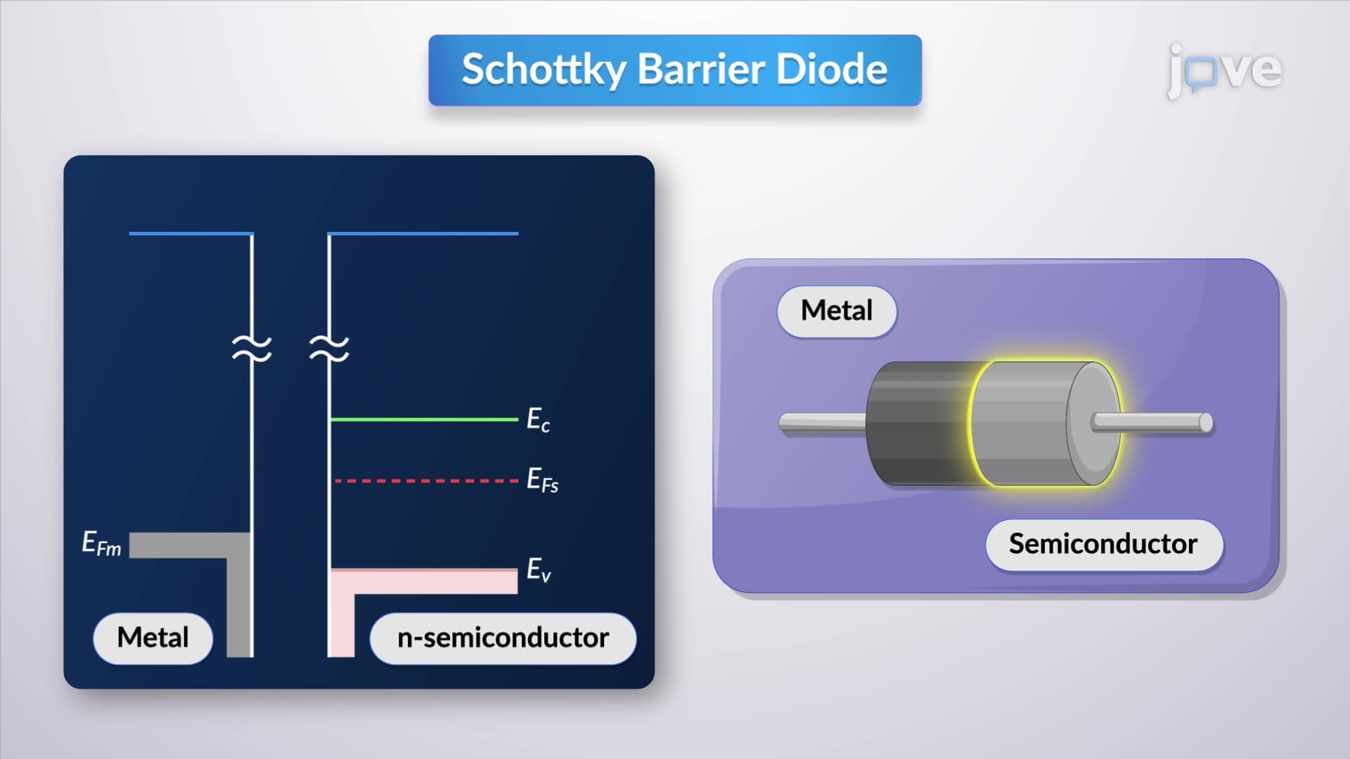
7. Schottky Barrier Diodes for High-Speed Switching Schottky diodes use metal-semiconductor junctions instead of p-n junctions, eliminating minority carrier storage effects that limit switching speed. Lower forward voltage drops (0.3-0.4V) reduce power dissipation compared to silicon diodes. The absence of charge storage enables switching frequencies well into the gigahertz range. US computer processors extensively use Schottky diodes in logic circuits where nanosecond switching times are critical. Power supplies for laptops and servers also employ Schottky rectifiers to improve efficiency by reducing conduction losses in high-frequency switching converters.