Loading video…


 14 Concepts
 16.1K views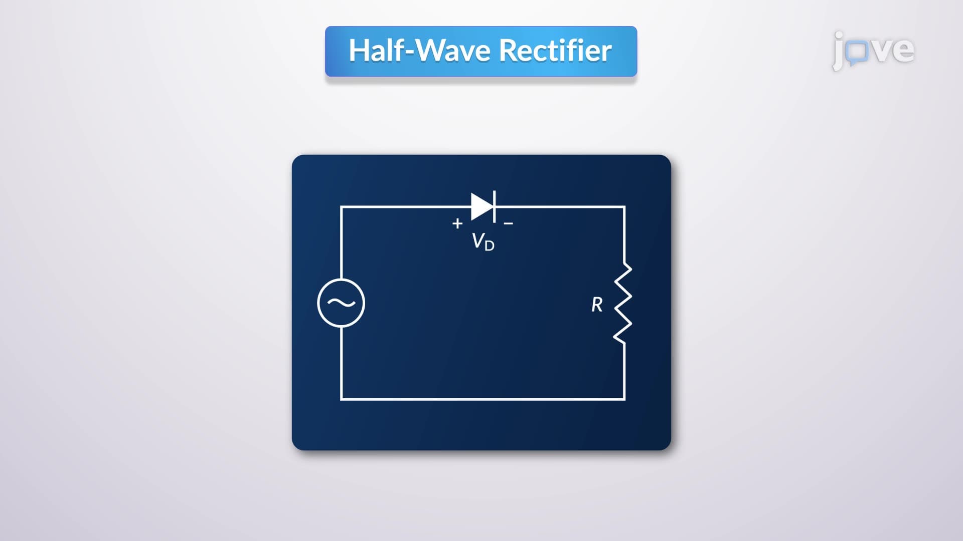

Video Summary: What Is Half Wave Rectifier
Ever wondered how your smartphone charger converts wall outlet AC power into the DC power your device needs? A full wave rectifier is the key component that makes this everyday electronics magic possible, though understanding starts with simpler half wave rectifier circuits. In US power grids delivering 120V AC, rectifiers in every electronic device from laptops to LED lights perform this critical AC-to-DC conversion. What is Half Wave Rectifier becomes clearer when you see how a single diode blocks negative voltage cycles while allowing positive ones through. Watch the full video on JoVE Coach to master this concept with expert-led visuals and step-by-step explanations.
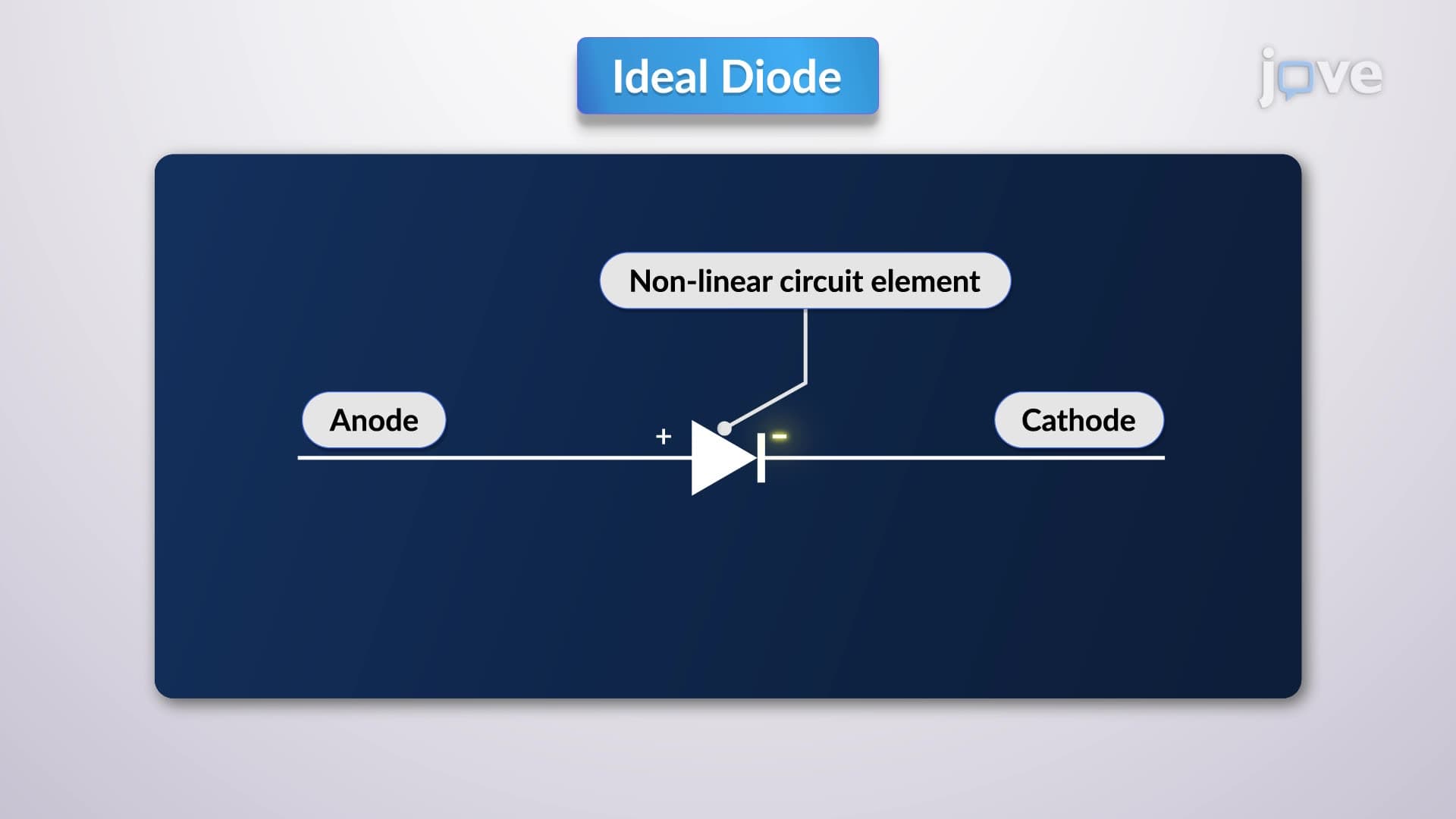
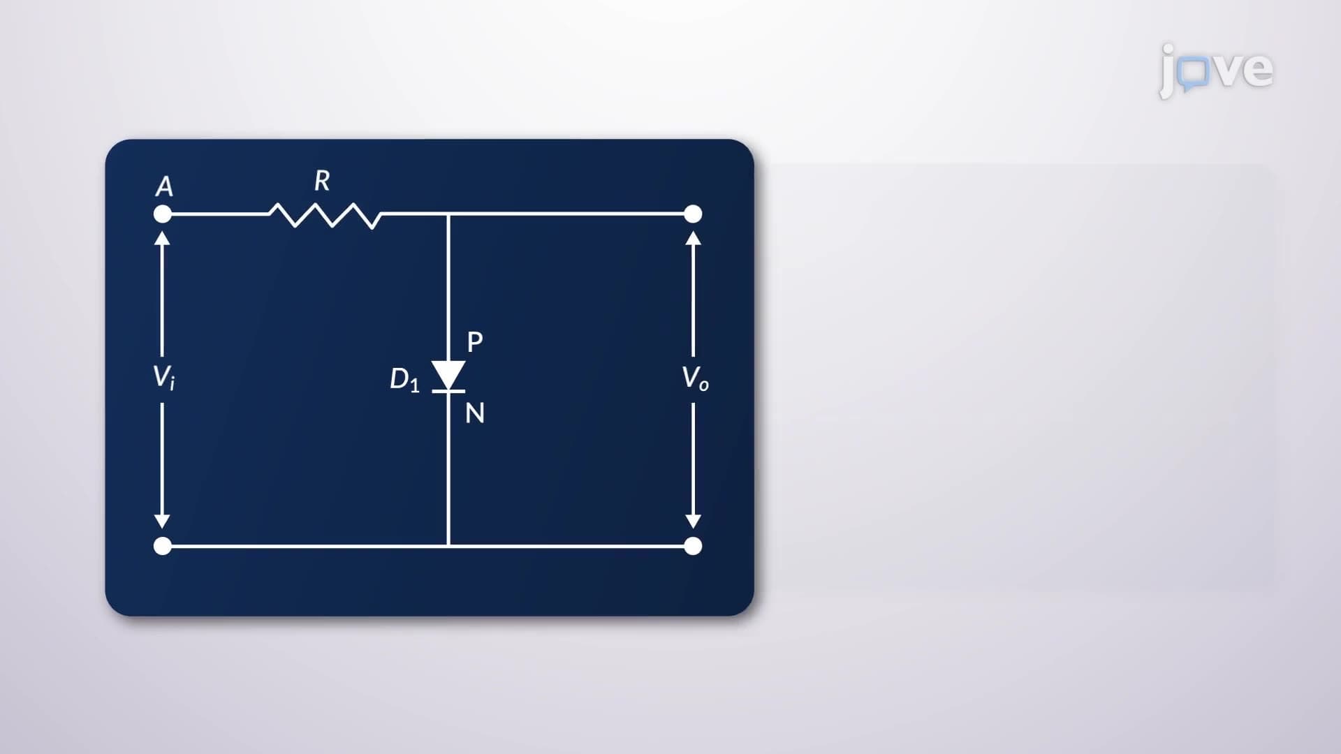
A half wave rectifier represents the simplest form of AC-to-DC conversion circuit, serving as the foundation for understanding more complex full wave rectifier designs. This basic circuit consists of just three essential components: an AC voltage source, a single semiconductor diode, and a load resistor connected in series. The full wave rectifier definition builds upon these same principles but uses additional components to capture both positive and negative half-cycles.
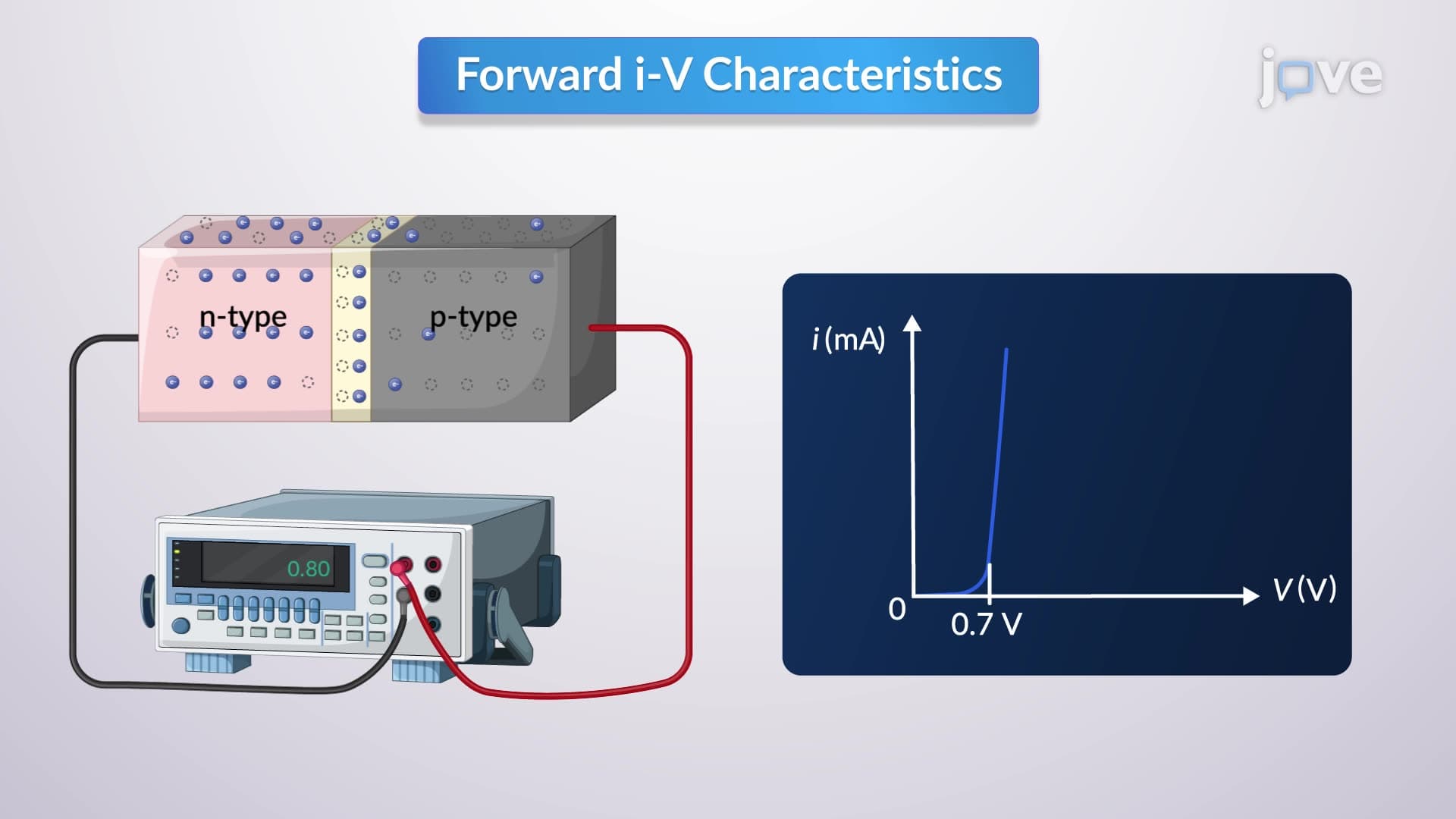
During the positive half-cycle of the input AC waveform, the diode becomes forward-biased when the input voltage exceeds the diode's forward voltage drop (typically 0.7V for silicon diodes). Current flows through the circuit, and the output voltage equals the input voltage minus the diode's voltage drop. This creates the characteristic full wave rectifier overview principle where electrical energy flows in only one direction.
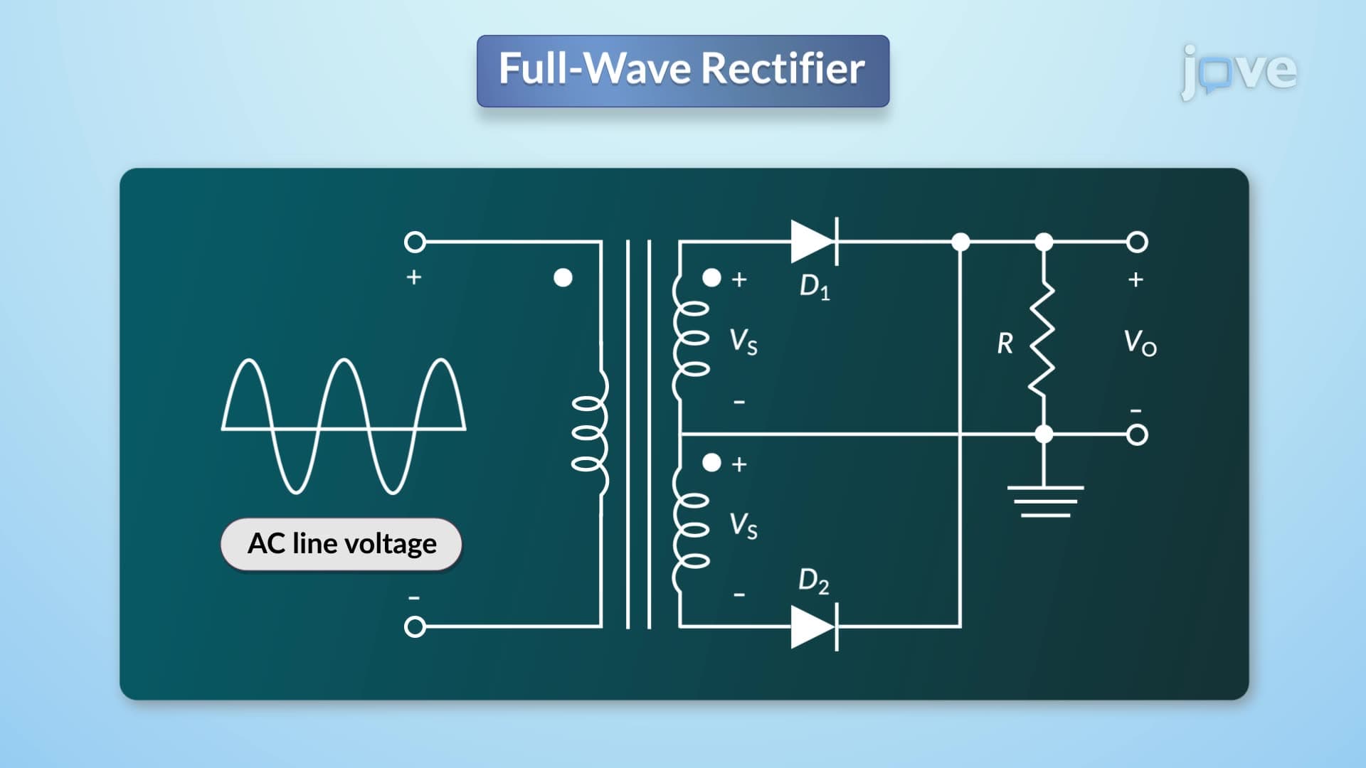
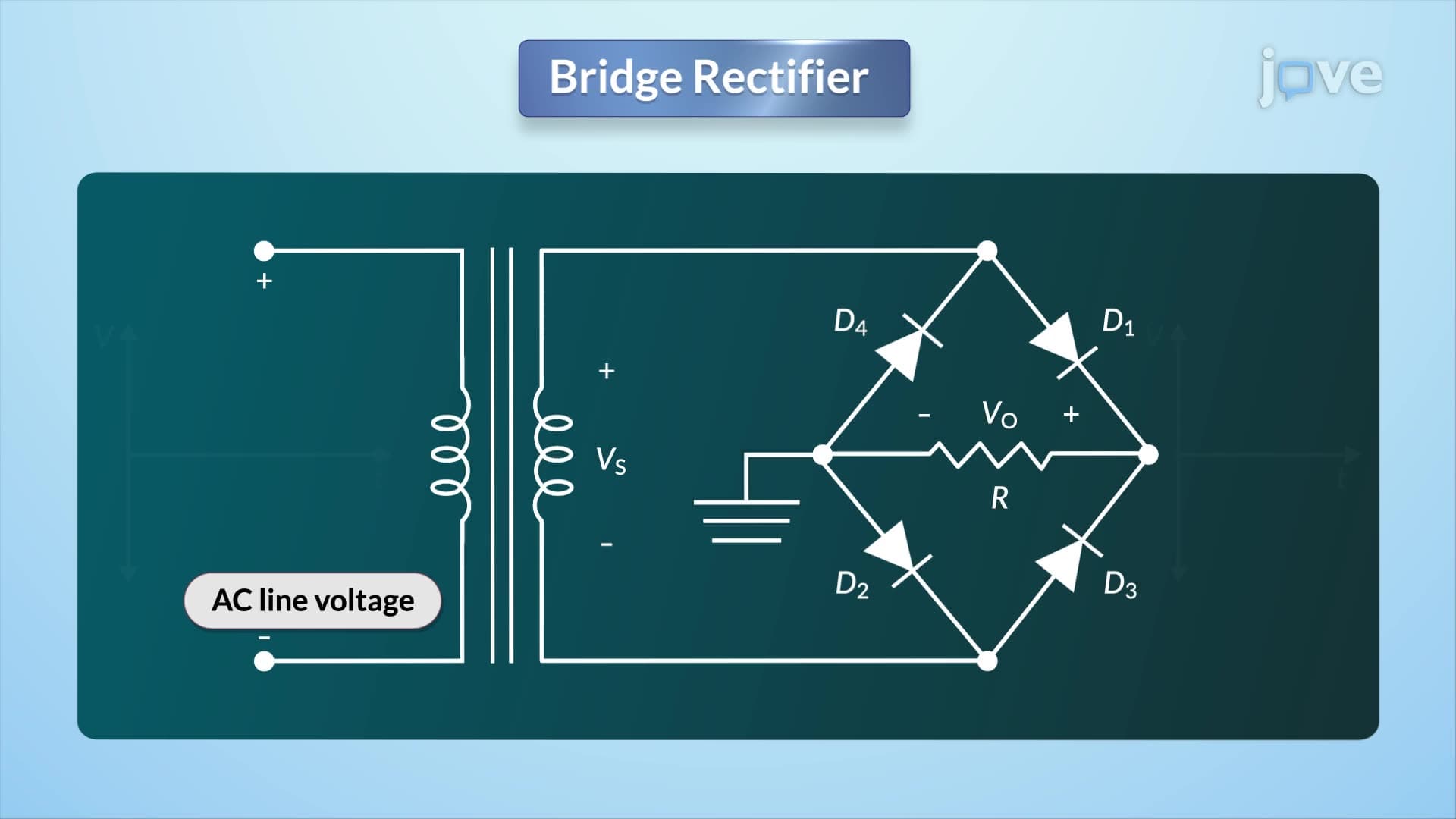
Conversely, during negative half-cycles, the input voltage reverse-biases the diode, effectively creating an open circuit. No current flows, resulting in zero output voltage. This fundamental operation explains what is full wave rectifier in detail - it's an advancement that captures energy from both half-cycles rather than wasting the negative portions.
The peak inverse voltage (PIV) specification becomes critical in rectifier design, especially for US applications handling standard 120V RMS household current (approximately 170V peak). During negative half-cycles, the diode must withstand the full peak input voltage in reverse bias without breaking down. Engineers typically select diodes with PIV ratings significantly higher than expected peak voltages to ensure reliability.
Half-wave rectifiers appear in simple applications like battery chargers for small devices, LED drivers, and basic power supplies where efficiency isn't paramount. For AP Physics students and college engineering majors, understanding these circuits provides essential groundwork for analyzing more sophisticated full wave rectifier concepts. The mathematical analysis involves calculating average and RMS output voltages, ripple factors, and transformer utilization factors - topics frequently appearing on MCAT physics sections and engineering midterm exams.
The full wave rectifier study guide approach often begins with mastering half-wave principles, as the same semiconductor physics and circuit analysis techniques apply. Students at institutions like MIT, Stanford, and Georgia Tech encounter these circuits in introductory electronics courses, where understanding full wave rectifier operation builds directly from half-wave fundamentals.
Related Micro-courses