Loading video…


 14 Concepts
 16.1K views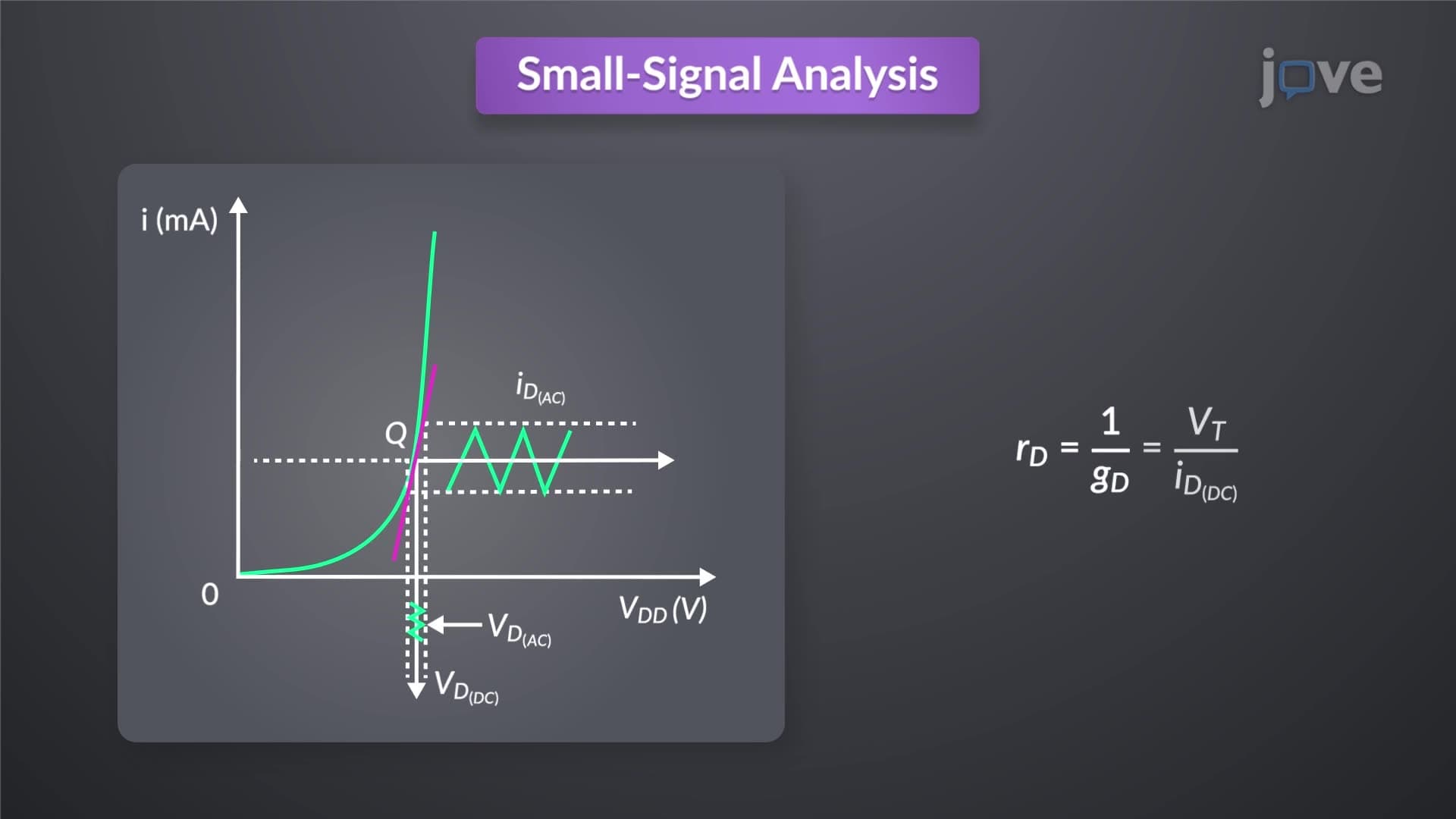

Video Summary: What Is Small Signal Diode Model
When your smartphone's radio frequency circuits process millions of signal variations per second, the modeling of diode reverse characteristics becomes crucial for maintaining signal integrity. The small signal diode model transforms the complex exponential behavior of diodes into manageable linear approximations, enabling engineers at companies like Qualcomm and Intel to design precise amplifier circuits. This linearization technique works when signal amplitudes remain much smaller than thermal voltage, creating predictable current-voltage relationships around the operating point. Watch the full video on JoVE Coach to master this concept with expert-led visuals and step-by-step explanations.
The small signal diode model represents one of the most fundamental concepts in semiconductor electronics, transforming the inherently nonlinear exponential behavior of PN junction diodes into manageable linear circuit elements. This modeling technique proves essential for analyzing AC signals in electronic systems, from the RF stages in cellular base stations operated by Verizon and AT&T to the audio amplifiers found in professional recording equipment used at studios like Abbey Road's US facilities.
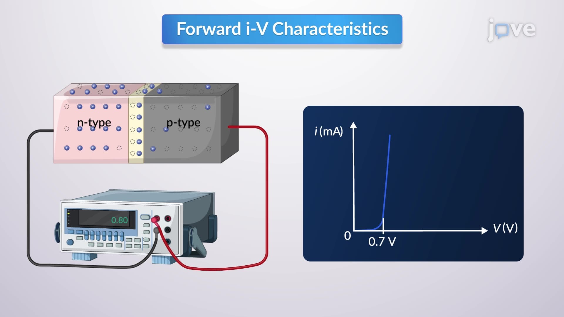
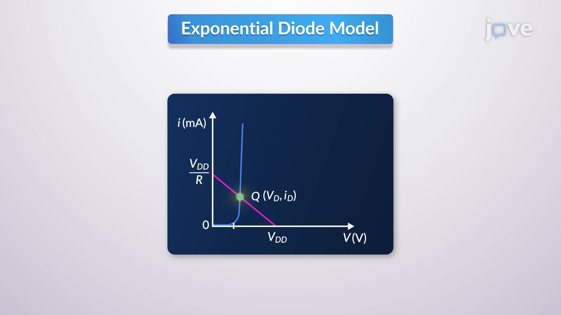
Every small signal analysis begins with establishing the DC operating point, commonly called the Q-point (quiescent point). At this point, the diode operates with a specific bias current ID determined by the DC supply voltage and circuit resistance. The exponential I-V characteristic curve of the diode creates a unique slope at this operating point, defining the small signal conductance gs = dI/dV. This slope represents how sensitive the diode current becomes to small voltage variations around the Q-point.
Students preparing for AP Physics or college-level electronics courses should understand that the Q-point selection directly impacts the small signal parameters. For instance, increasing the bias current raises the small signal conductance, making the diode more responsive to AC signals but also increasing power consumption.
The small signal resistance, also termed incremental resistance (r), equals the inverse of small signal conductance. This parameter follows the fundamental relationship r = VT/ID, where VT represents thermal voltage (approximately 26 millivolts at room temperature) and ID represents the DC bias current. This formula appears frequently on MCAT physics sections and electrical engineering midterm examinations across universities like MIT and Stanford.
The thermal voltage concept connects directly to semiconductor physics principles. As temperature increases, VT rises proportionally, affecting the small signal resistance calculations. This temperature dependency explains why precision electronic instruments used in aerospace applications require temperature compensation circuits.
When signal amplitudes remain significantly smaller than thermal voltage (typically less than 5-10 mV), the exponential characteristic curve appears nearly linear over the signal's operating range. This linearization enables engineers to apply superposition principles, separating DC bias analysis from AC signal analysis. The total diode current becomes the simple sum of DC bias current plus AC signal current, dramatically simplifying circuit calculations for complex systems like the signal processing stages in medical imaging equipment used at hospitals such as Mayo Clinic and Johns Hopkins.
Related Micro-courses