Loading video…


 14 Concepts
 16.1K views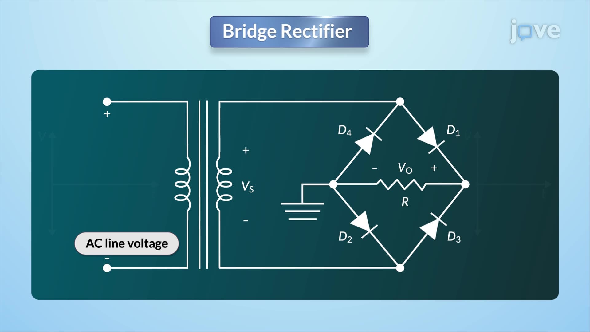

Video Summary: What Is Bridge Rectifier
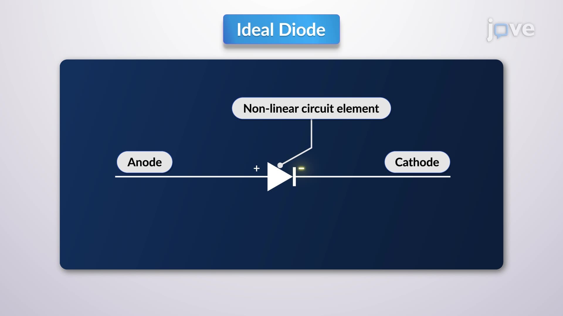
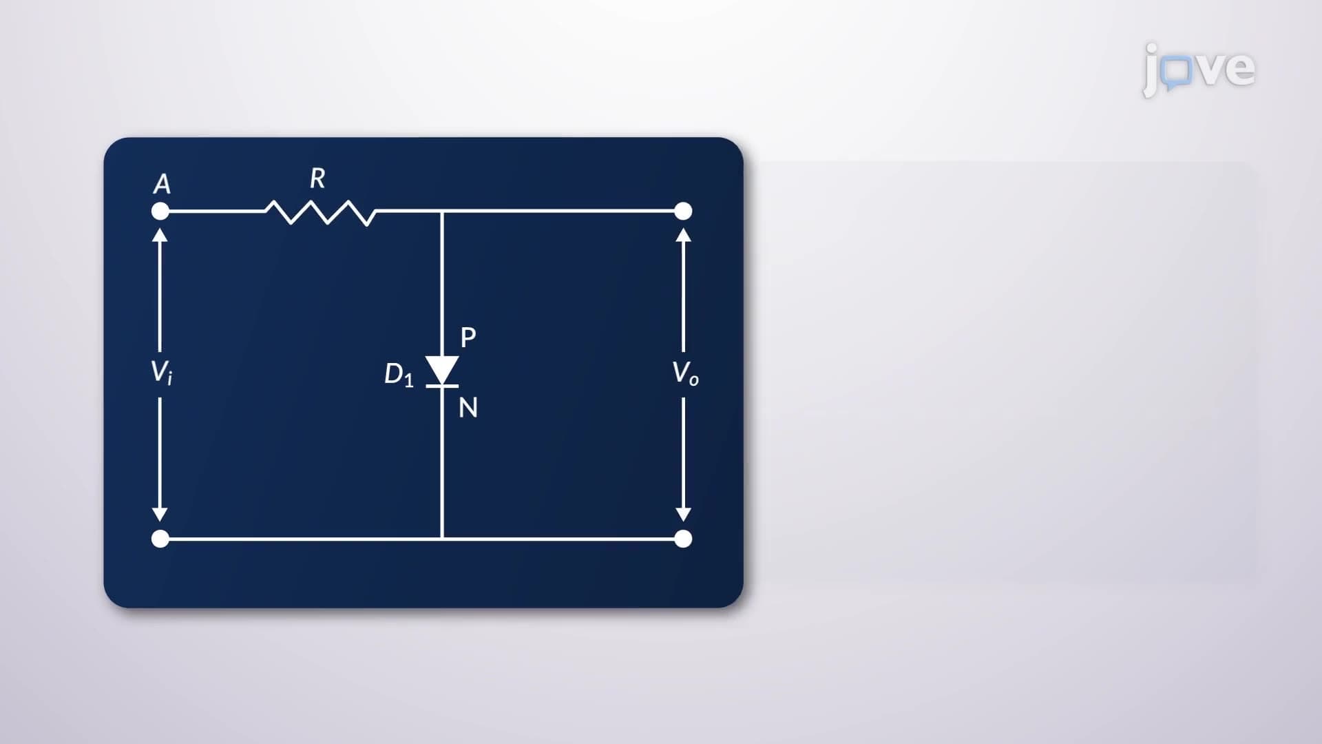
Why do your smartphone chargers convert wall outlet AC power into smooth DC power so efficiently? A clipper circuit, specifically the bridge rectifier configuration, makes this everyday miracle possible by using four strategically arranged diodes to capture both positive and negative voltage cycles. Consider how Apple's iPhone chargers, found in millions of US homes, rely on this exact bridge rectifier principle to deliver consistent 5V DC power from 120V AC household current. What is bridge rectifier technology becomes clear when you see its elegant four-diode design in action. Watch the full video on JoVE Coach to master this concept with expert-led visuals and step-by-step explanations.
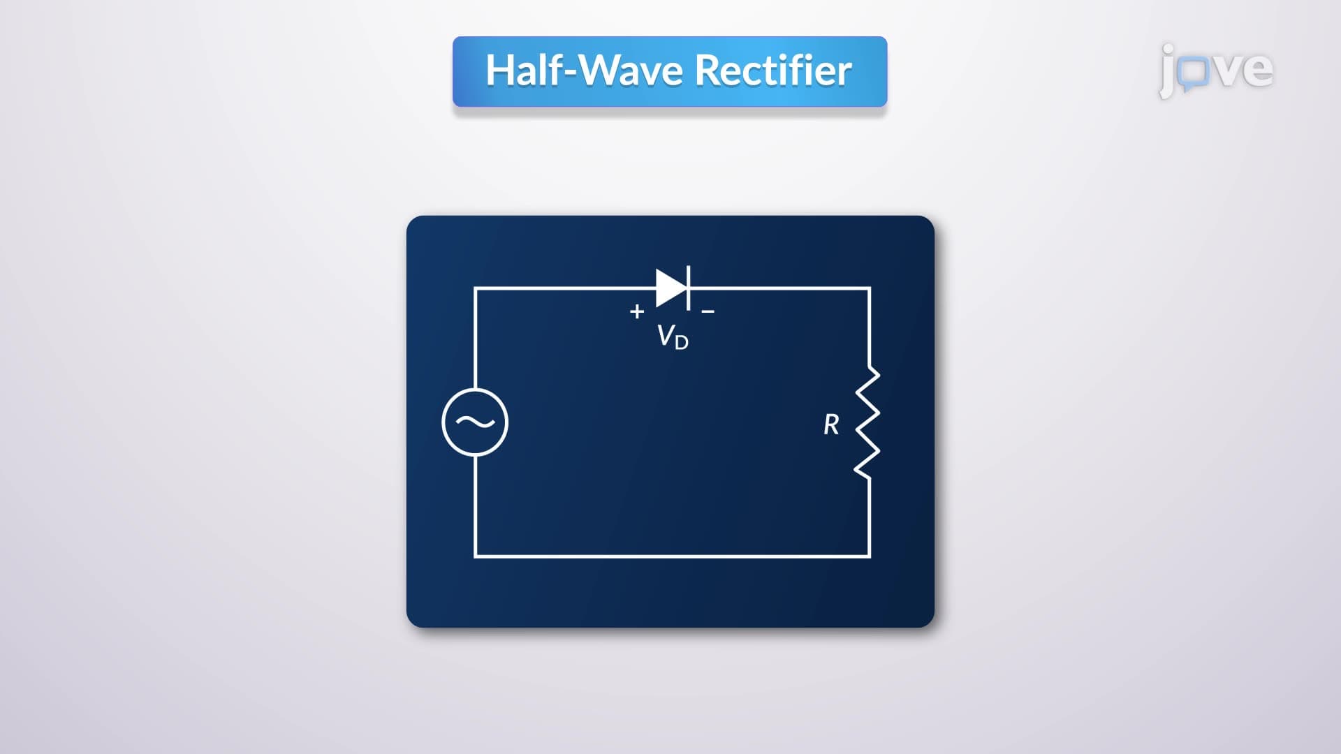
What is bridge rectifier technology represents one of electronics' most elegant solutions for AC-to-DC conversion. Unlike single-diode half-wave rectifiers that waste 50% of the input signal, bridge rectifiers capture energy from both positive and negative voltage cycles. This full-wave rectification principle appears throughout US engineering curricula, from high school AP Physics courses to university-level electrical engineering programs.
The bridge configuration's genius lies in its symmetrical four-diode arrangement. When AC voltage enters the circuit, diagonal diode pairs alternate conduction based on input polarity. During positive half-cycles, current flows through the load via one diagonal path, while the opposing diagonal conducts during negative cycles. This switching action maintains consistent current direction through the load resistor, creating unidirectional (though pulsating) DC output.
Bridge rectifier operation follows predictable patterns that students encounter on college midterms and professional certification exams. During positive input voltage, diodes positioned at opposite corners of the "bridge" become forward-biased, creating a complete circuit path. The remaining two diodes experience reverse bias, effectively removing themselves from the circuit until the next half-cycle.
This alternating conduction pattern explains why bridge rectifiers achieve approximately 81.2% efficiency-significantly higher than center-tapped alternatives. US electronics manufacturers like Texas Instruments and Analog Devices incorporate this principle into power management integrated circuits found in everything from laptop adapters to industrial motor controllers.
Peak Inverse Voltage (PIV) calculations frequently appear on electrical engineering licensing exams across the US. For bridge rectifiers, each diode must withstand approximately 1.414 times the RMS input voltage when reverse-biased. This relatively low PIV requirement (compared to center-tapped designs) allows engineers to use standard-rated components, reducing costs and improving reliability.
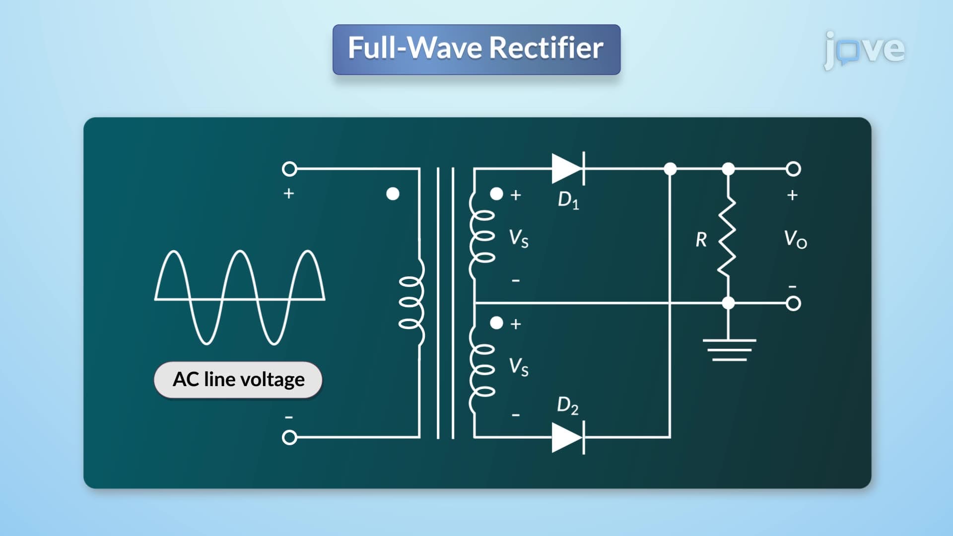
The transformer design advantages become apparent in practical applications. Bridge configurations eliminate the need for center-tapped secondaries, allowing smaller, lighter transformers. This efficiency gain explains why consumer electronics companies choose bridge rectifiers for compact devices where space and weight matter.
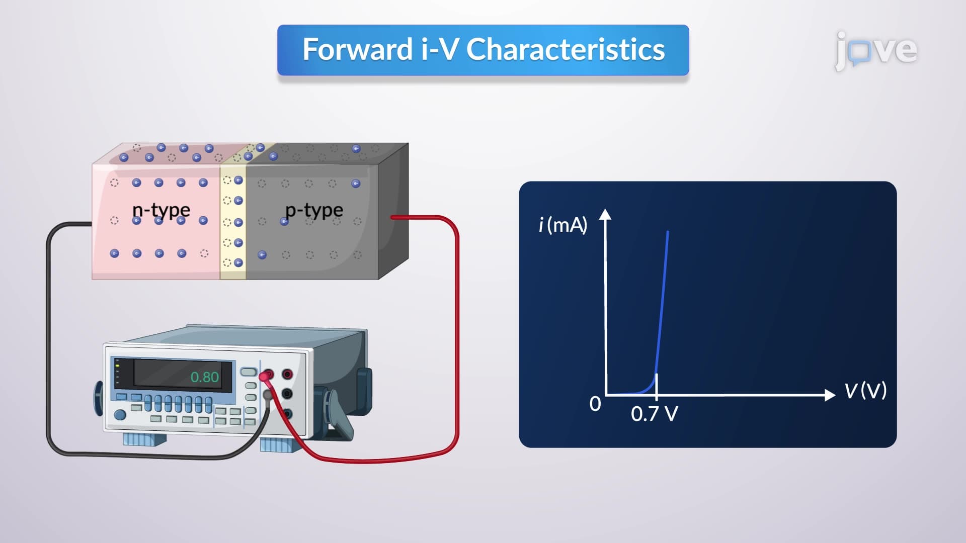
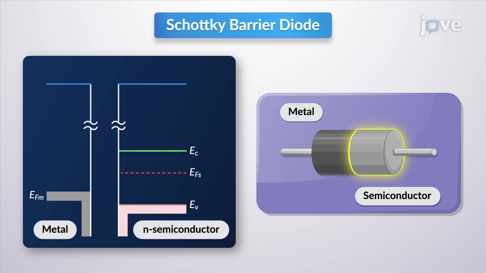
Modern bridge rectifier implementations often incorporate Schottky diodes to reduce forward voltage drop from 0.7V to approximately 0.3V per silicon diode. This 0.4V improvement per conducting diode pair significantly boosts overall efficiency, especially in low-voltage applications common in computer power supplies.
Capacitor filtering represents another crucial enhancement covered in AP Physics C and college circuit analysis courses. Adding a filter capacitor across the output reduces ripple voltage, creating smoother DC suitable for sensitive electronic circuits. The time constant calculations (RC) determine filtering effectiveness-concepts that appear regularly on standardized physics assessments.
Related Micro-courses