Loading video…


 14 Concepts
 16.1K views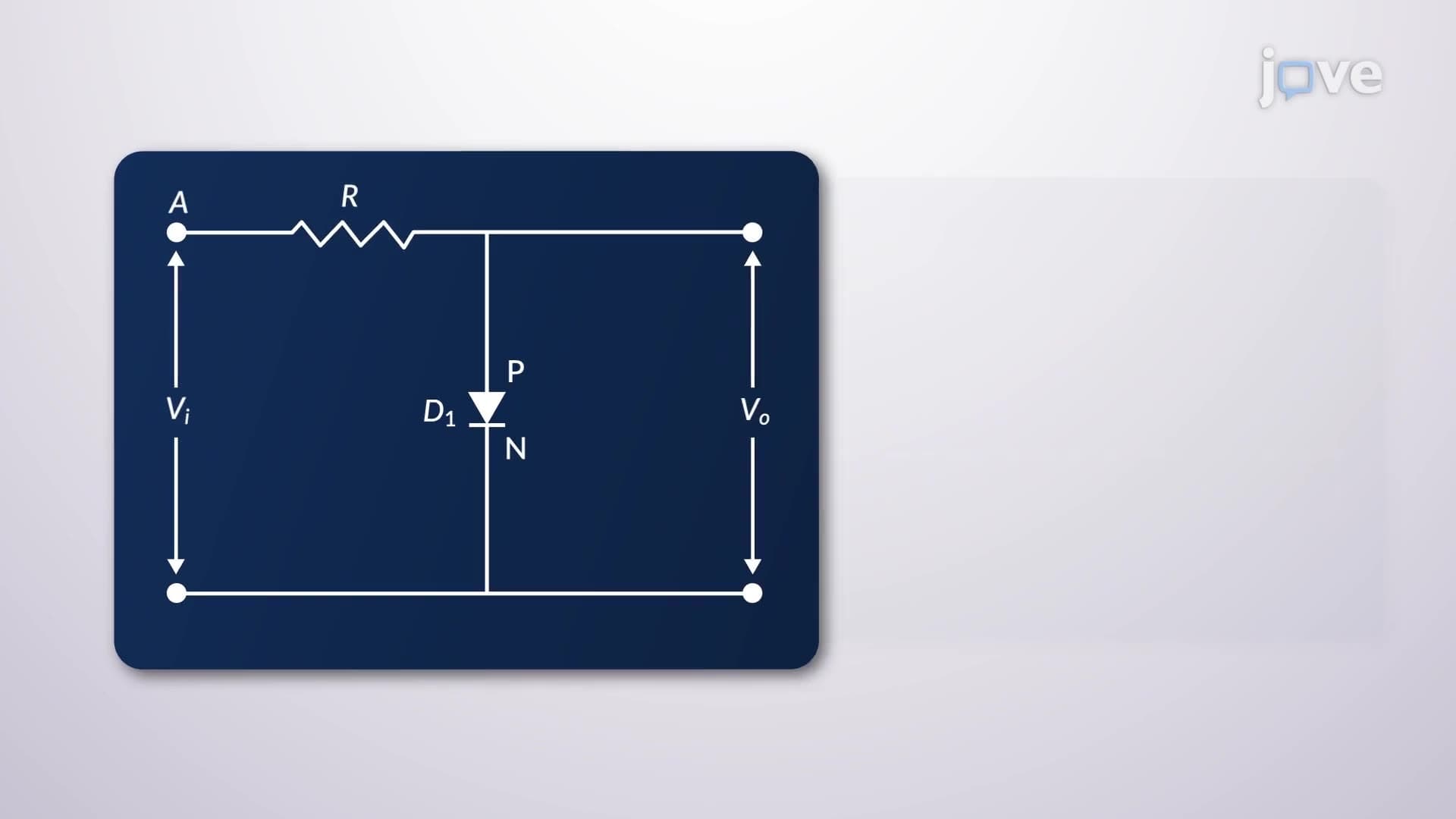

Video Summary: What Is Clipper Circuit
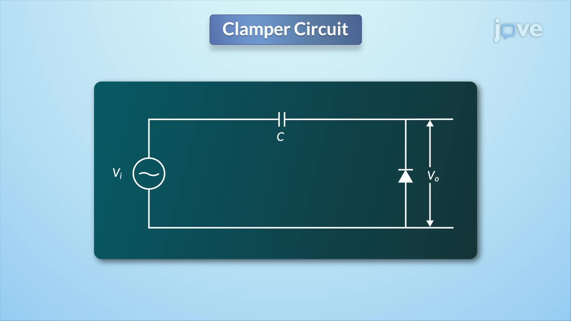
Ever wondered how your smartphone protects its delicate circuits from voltage spikes? A clamper circuit is an electronic wave-shaping device that uses diodes to limit voltage levels and protect sensitive components. These circuits are essential in everything from automotive electronics to medical equipment like MRI machines across US hospitals. Understanding what is clamper circuit opens the door to grasping how modern electronics maintain signal integrity and prevent damage. Watch the full video on JoVE Coach to master this concept with expert-led visuals and step-by-step explanations.
A clipper circuit represents a fundamental wave-shaping tool in electronics that deliberately removes or "clips" portions of input signals that exceed predetermined voltage levels. This clamper circuit definition encompasses both positive and negative clipping capabilities, making these devices essential for signal conditioning and circuit protection. Unlike amplifiers that boost signals, clipper circuits intentionally limit signal amplitude to prevent damage to downstream components.
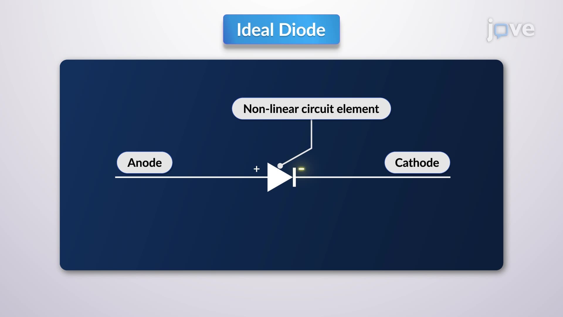
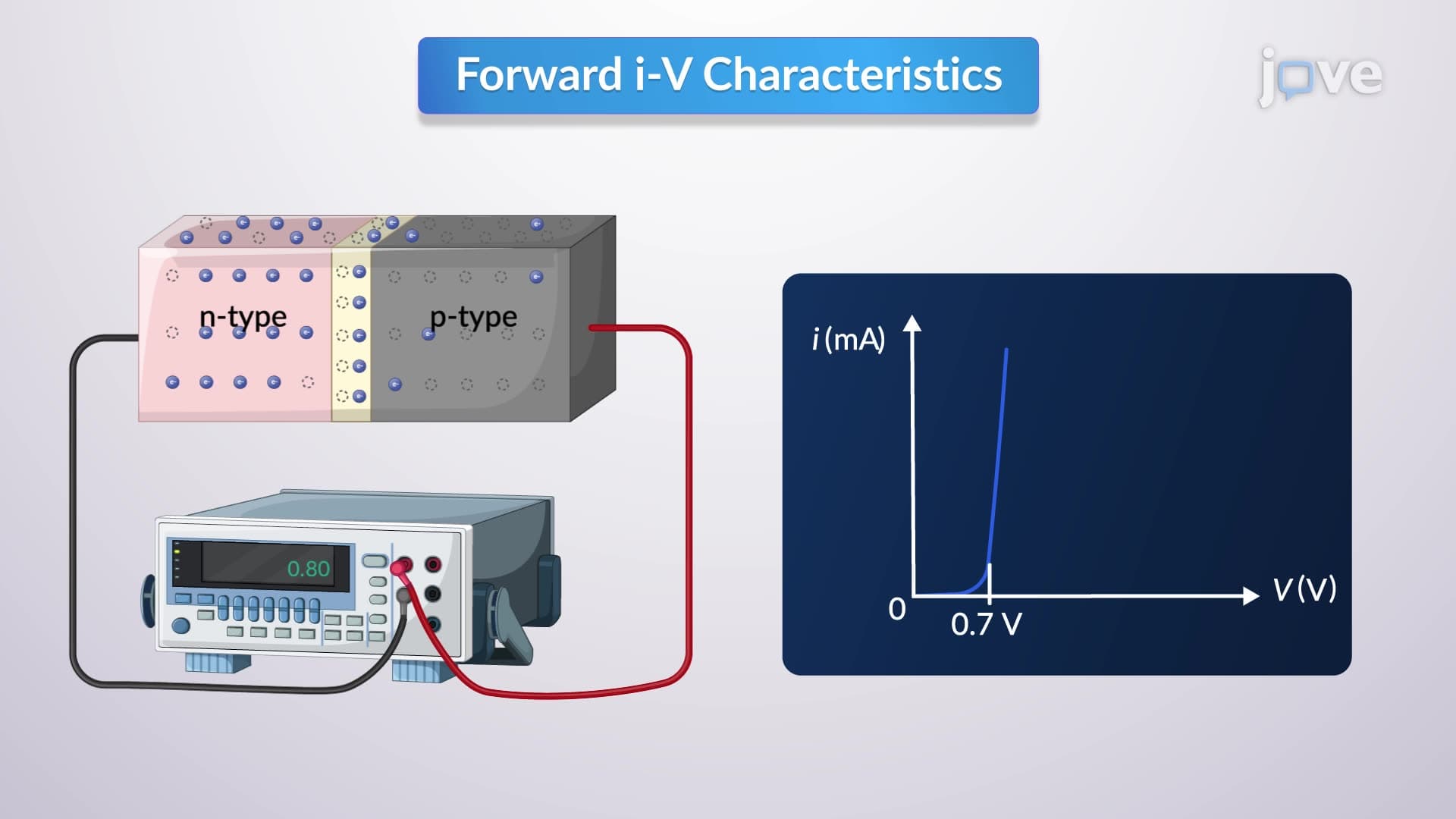
The clamper circuit concept revolves around the strategic use of diodes as voltage-controlled switches. When examining what is clamper circuit in detail, we discover that diodes conduct current in one direction when forward-biased and block current when reverse-biased. This fundamental semiconductor behavior enables precise control over which portions of AC waveforms pass through to the output.
Understanding clamper circuit basics requires examining how dual-clipper configurations work during different signal phases. During the positive half-cycle, diode D1 experiences competing influences: the input signal attempts to forward-bias it while the biasing battery creates reverse-bias. The net effect determines whether clipping occurs. When input voltage remains below the biasing threshold, D1 stays off, allowing the signal to pass unchanged. However, once input voltage exceeds this threshold, D1 conducts, effectively short-circuiting the excess voltage and maintaining output at the biasing level.
This clamper circuit overview becomes more complex during negative half-cycles when roles reverse. Diode D2 now becomes the active clipping element, limiting negative voltage excursions according to its biasing voltage. The precise resistance value selection ensures adequate forward current for reliable diode operation while minimizing reverse leakage current that could affect signal integrity.
Students preparing for AP Physics C or college-level electronics courses encounter clipper circuits in power supply design, signal processing, and protection circuit analysis. US universities like MIT and Stanford emphasize these concepts in their electrical engineering curricula because clipper circuits appear in countless applications from automotive ignition systems to medical device protection circuits.
Major US electronics manufacturers including Texas Instruments and Analog Devices incorporate clipper circuit principles into their integrated circuit designs for voltage regulation and signal conditioning. This clamper circuit study guide perspective helps students connect theoretical knowledge with practical industry applications they'll encounter in engineering careers or advanced coursework.
Related Micro-courses