Loading video…


 14 Concepts
 16.1K views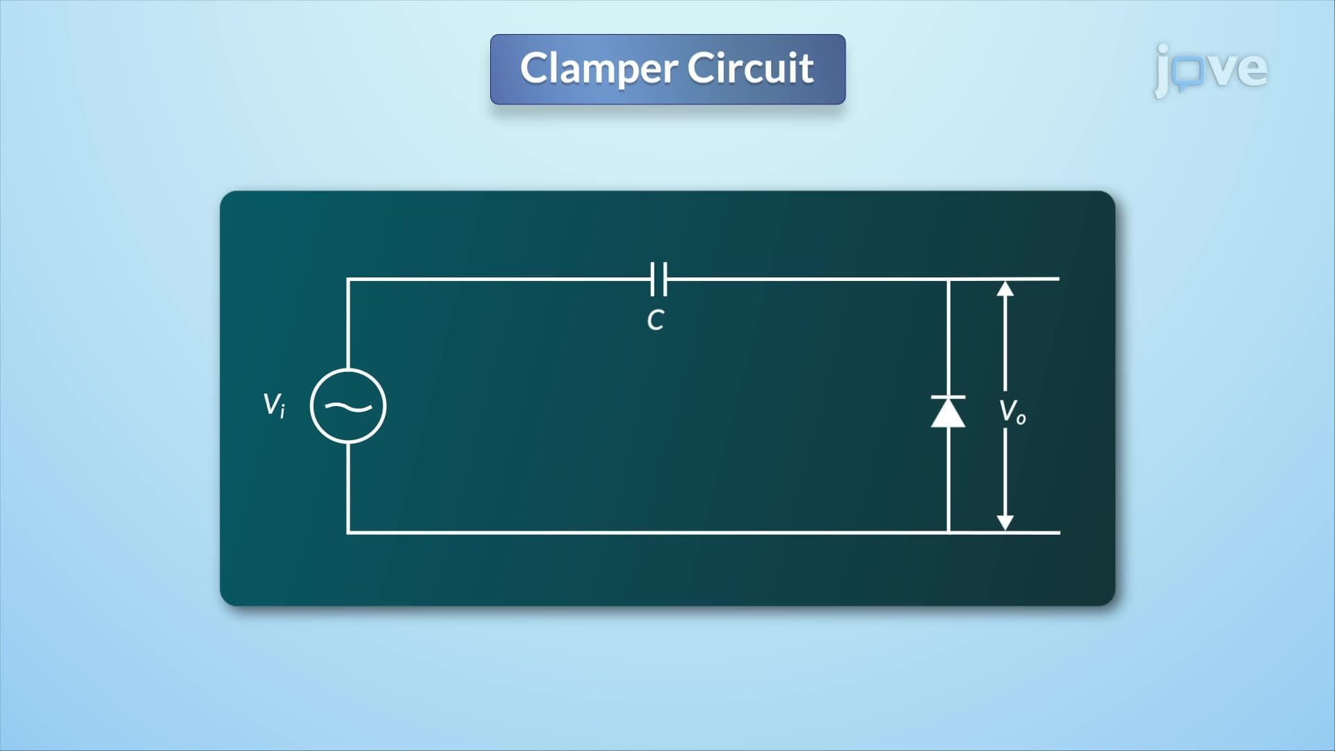

Video Summary: What Is Clamper Circuit
Ever wondered how your smartphone charger transforms AC voltage from wall outlets into steady DC power? A voltage doubler circuit uses clever engineering principles similar to clamper circuits to multiply input voltages without transformers. These circuits appear everywhere in electronics-from camera flash units in professional photography studios to power supplies in medical equipment across US hospitals. Understanding what is clamper circuit reveals the foundation behind voltage multiplication techniques that power countless devices around us. Watch the full video on JoVE Coach to master this concept with expert-led visuals and step-by-step explanations.
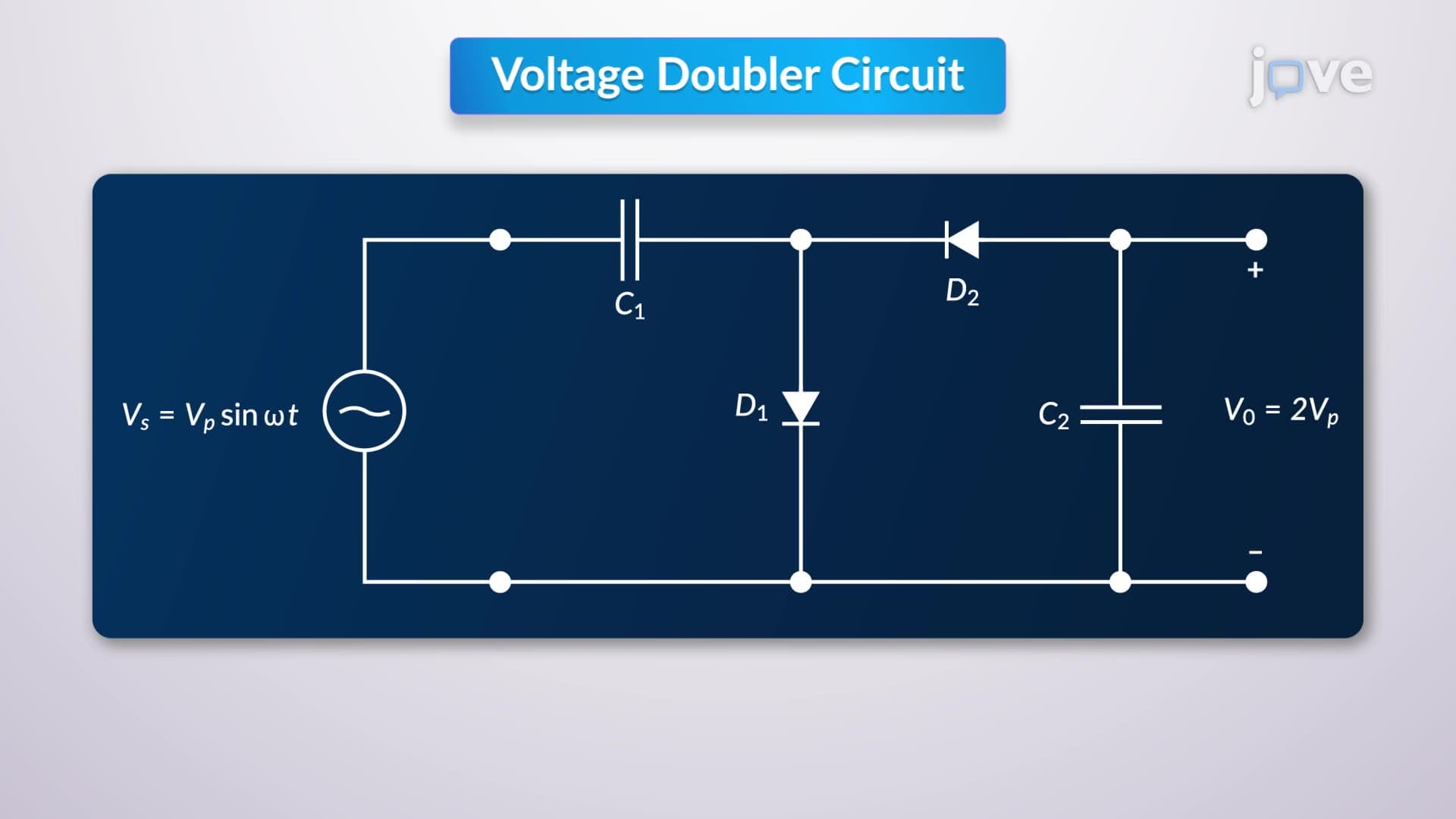
A voltage doubler circuit represents a specialized type of clamper circuit that effectively doubles the input voltage amplitude while shifting its DC level. These circuits operate on the fundamental principle of energy storage in capacitors combined with the rectifying action of diodes. Unlike transformers that require magnetic coupling, voltage doubler circuits achieve voltage multiplication through purely electronic switching and energy storage mechanisms.
The voltage doubler circuit definition encompasses any circuit configuration that produces an output voltage approximately twice the peak input voltage. This multiplication occurs through a two-phase process: energy storage during one half-cycle and energy delivery during the opposite half-cycle. The capacitor acts as a temporary energy reservoir, while the diode provides directional control of current flow.
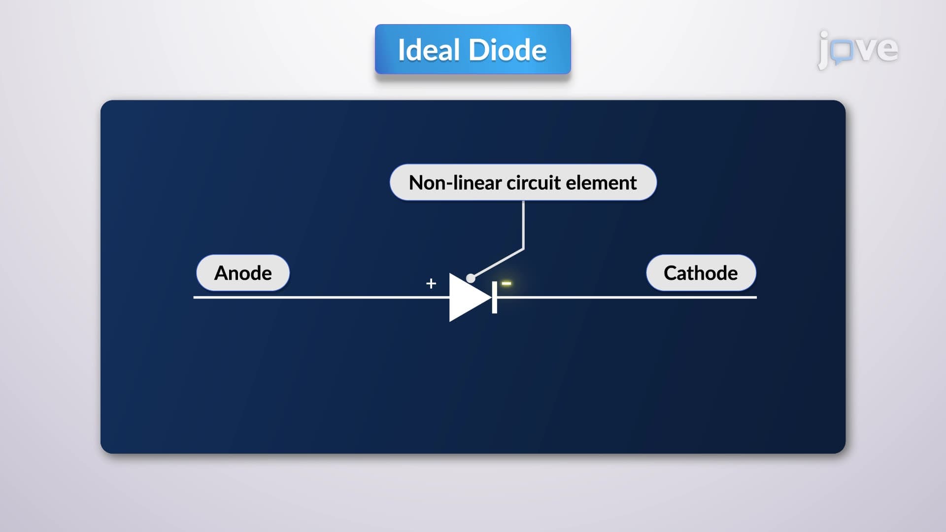
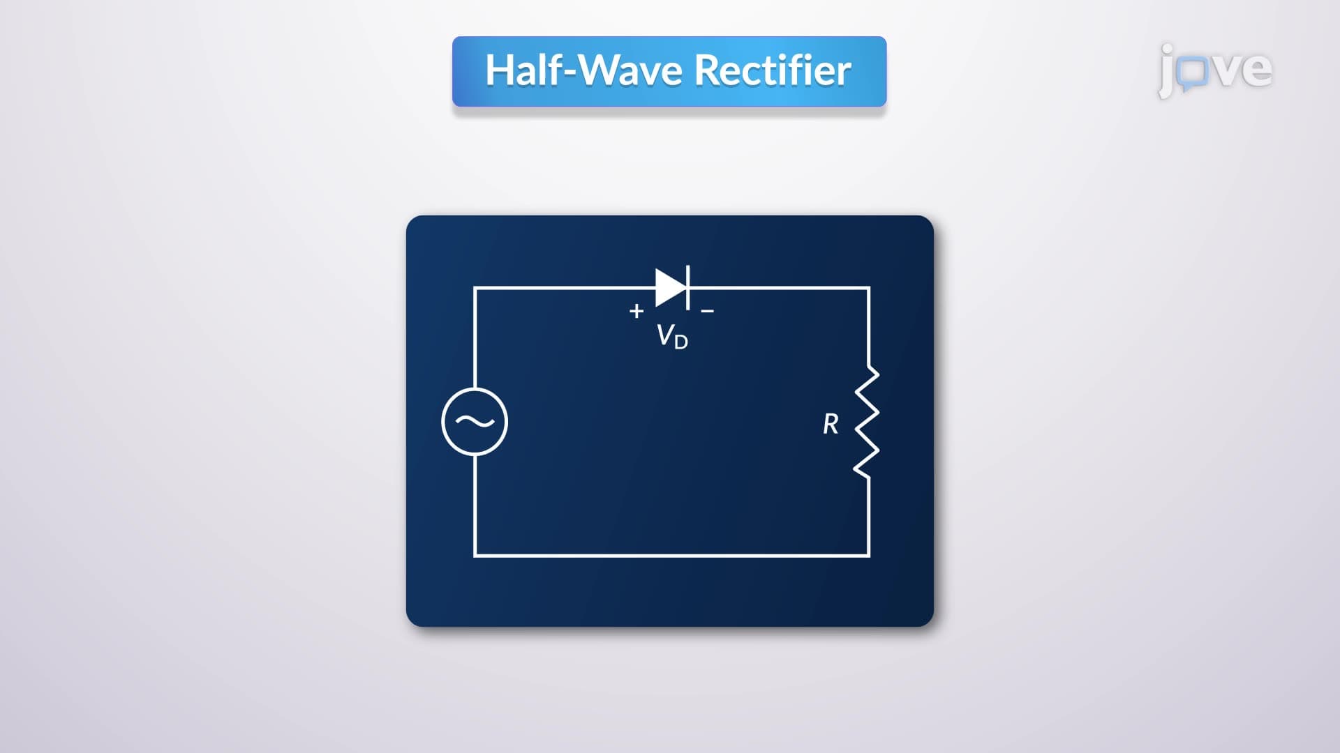
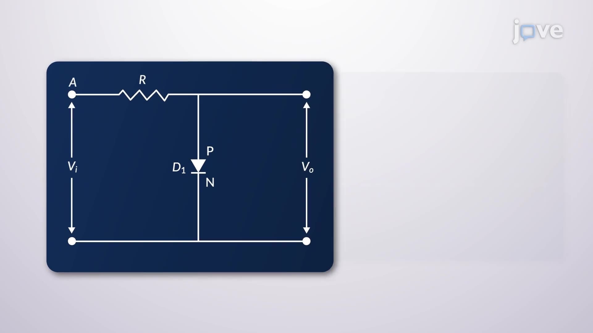
When examining what is voltage doubler circuit in detail, we must consider both the charging and discharging phases. During the negative half-cycle of the input waveform, the diode conducts (forward-biased), creating a low-resistance path. The capacitor charges to the peak input voltage value, storing electrical energy. The output voltage across the diode remains near zero during this phase due to the diode's forward voltage drop.
During the positive half-cycle, the diode becomes reverse-biased and blocks current flow. Now, the input voltage and the charged capacitor voltage add together in series, creating the voltage doubling effect. The output voltage across the diode equals the sum of the input voltage and the capacitor voltage, theoretically reaching twice the input peak voltage.
Real-world voltage doubler circuit overview applications must account for load resistance effects. When current flows through a connected load, the capacitor begins discharging according to the RC time constant. This discharge reduces the output voltage exponentially, creating a ripple effect. Engineers typically minimize this ripple by selecting large capacitance values or implementing additional filtering stages.
Temperature variations, component tolerances, and load fluctuations all impact circuit performance. In US medical device manufacturing, voltage doubler circuits must meet strict FDA regulations for stability and reliability. Similarly, consumer electronics applications require compliance with FCC electromagnetic interference standards.
Students preparing for AP Physics exams frequently encounter clamper and voltage doubler problems involving energy conservation and circuit analysis. College-level courses in electrical engineering programs at institutions like MIT and Stanford extensively cover these topics in circuit theory coursework. The MCAT occasionally includes questions about biological signal processing applications where clamper circuits restore DC levels in bioelectric measurements.
Professional applications span from high-voltage power supplies in X-ray machines at Mayo Clinic facilities to camera flash circuits used by photographers covering major league baseball games across US stadiums.
Related Micro-courses