Loading video…


 14 Concepts
 16.1K views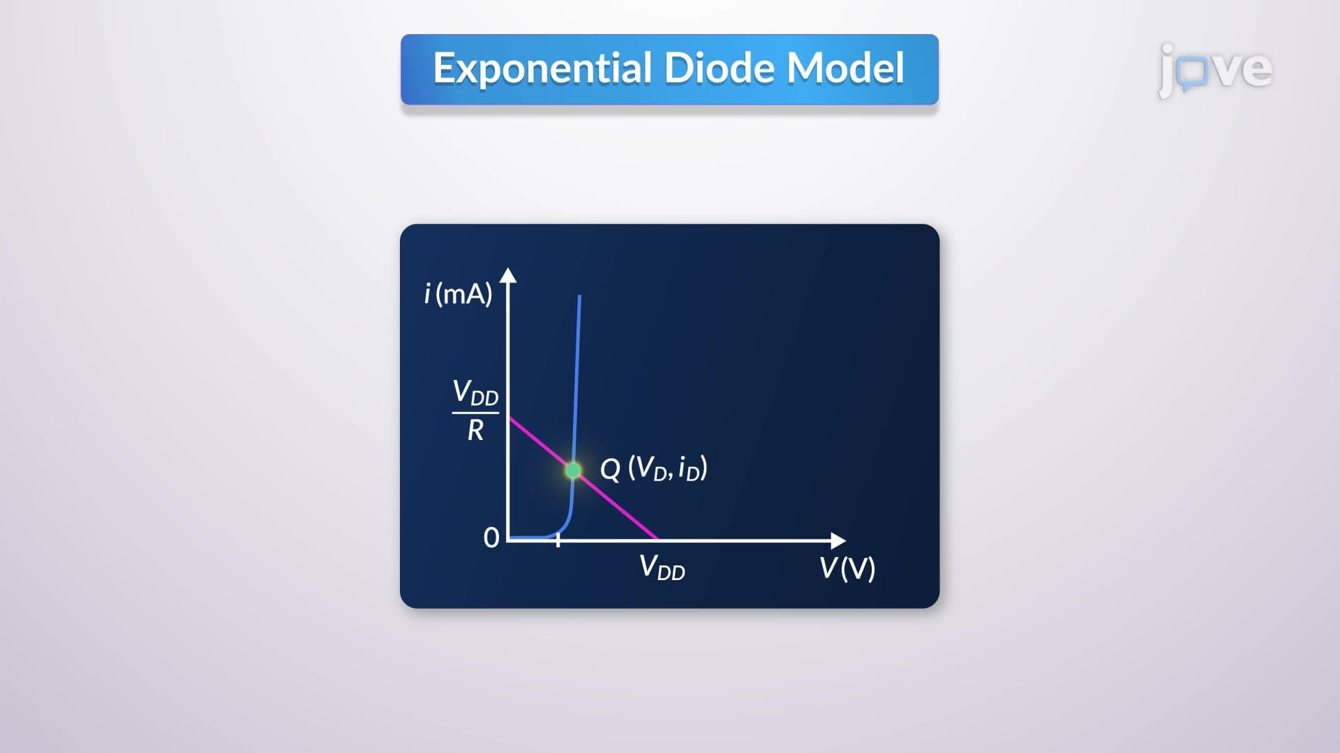

Video Summary: Modeling of Diode Forward Characteristics Explained
Ever wonder how your smartphone charger prevents electricity from flowing backward and damaging your device? The small signal diode model is the key to understanding this electronic protection, used in everything from Apple iPhone chargers to Tesla charging stations. Modeling of diode forward characteristics explained reveals how engineers predict diode behavior using exponential and constant-voltage-drop models, enabling precise circuit design for consumer electronics across America. Watch the full video on JoVE Coach to master this concept with expert-led visuals and step-by-step explanations.
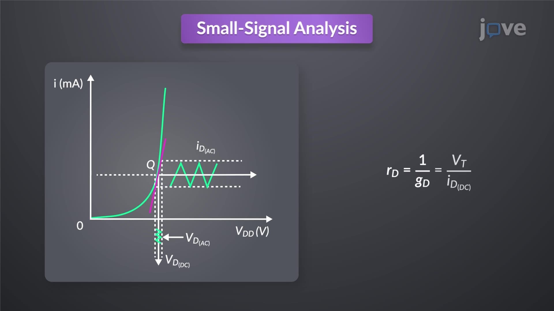
The small signal diode model represents one of the most fundamental concepts in electronics engineering, forming the backbone of circuit analysis taught in AP Physics courses and undergraduate electrical engineering programs nationwide. When a diode operates in forward bias-meaning current flows easily from anode to cathode-engineers must accurately predict its behavior to design reliable circuits found in everything from LED displays in Times Square to power supplies in NASA's space missions.
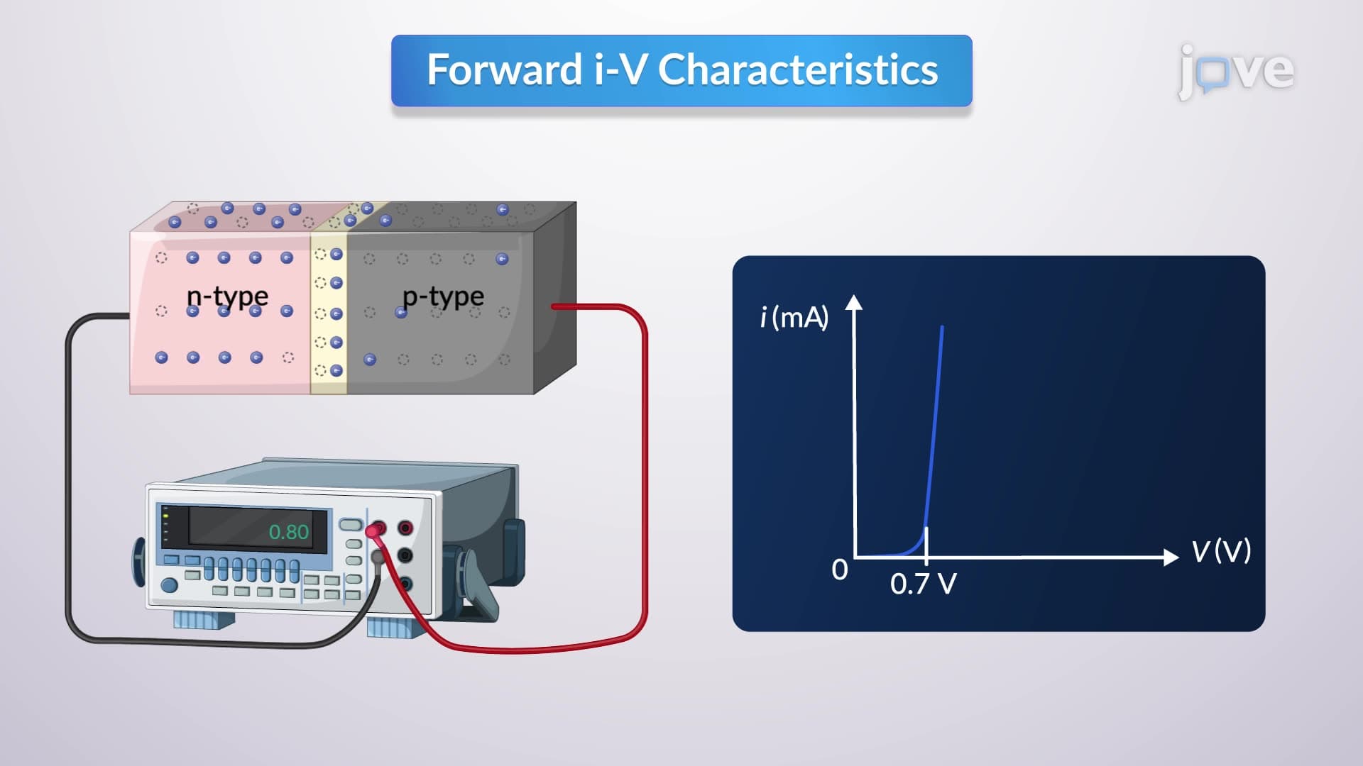
The exponential diode model provides the most accurate representation of diode behavior, particularly crucial when source voltages exceed 0.5 volts. This model recognizes that diode current increases exponentially with applied voltage, following the relationship I = Is(e^(V/nVt) - 1), where Is represents saturation current and Vt equals thermal voltage. Students preparing for the MCAT or AP Physics C exams frequently encounter this relationship, as it demonstrates how quantum mechanics governs macroscopic electronic behavior. In practical applications, companies like Intel use exponential modeling when designing microprocessor power management circuits where precise current predictions prevent chip damage.
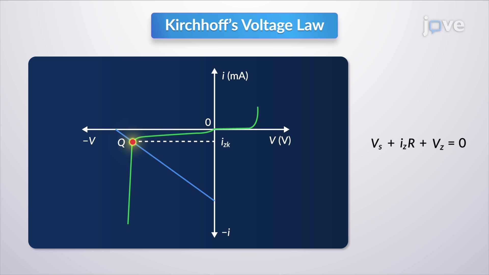
The intersection of the load line with the diode characteristic curve-point Q-reveals the actual operating conditions within any circuit. This graphical analysis technique, essential for college-level circuit analysis courses, transforms complex mathematical relationships into visual problem-solving tools. The load line equation, derived from Kirchhoff's voltage law, creates a straight line representing all possible combinations of diode voltage and current that satisfy the circuit constraints. Engineering students at institutions like MIT and Stanford regularly use this approach to solve complex power supply design problems.
For many practical applications, the constant-voltage-drop model simplifies analysis by assuming a fixed 0.7V forward voltage drop across silicon diodes. This approximation proves invaluable in preliminary circuit design and appears frequently on standardized tests including the FE exam for engineering professionals. Companies like General Electric rely on this simplified approach during initial circuit sketches, knowing that more detailed modeling can follow during final design phases. The 0.7V assumption works effectively when dealing with typical operating currents in consumer electronics.
Related Micro-courses