Loading video…


 14 Concepts
 16.1K views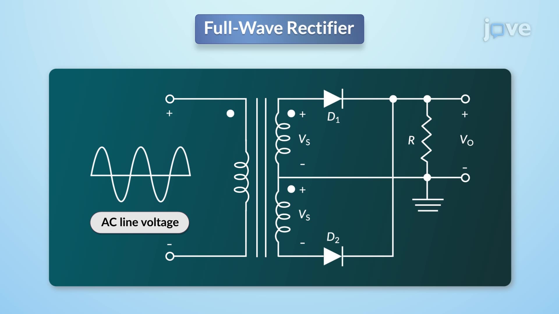

Video Summary: What Is Full Wave Rectifier
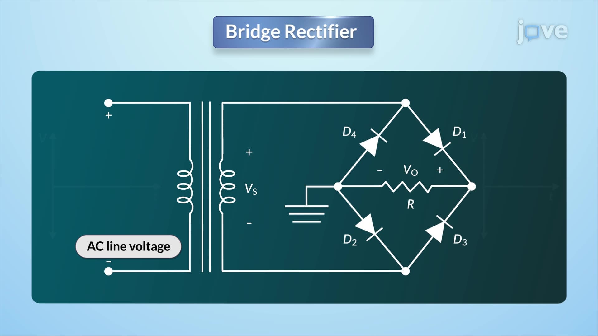
Ever wonder how your smartphone charger converts AC power from the wall outlet into DC power for your device? A bridge rectifier makes this possible by efficiently converting alternating current to direct current using four diodes in a diamond configuration. Unlike simpler rectification methods, the bridge rectifier design eliminates the need for center-tapped transformers while achieving superior efficiency-making it the preferred choice in modern power supplies from laptop chargers to electric vehicle charging stations across the United States. Watch the full video on JoVE Coach to master this concept with expert-led visuals and step-by-step explanations.
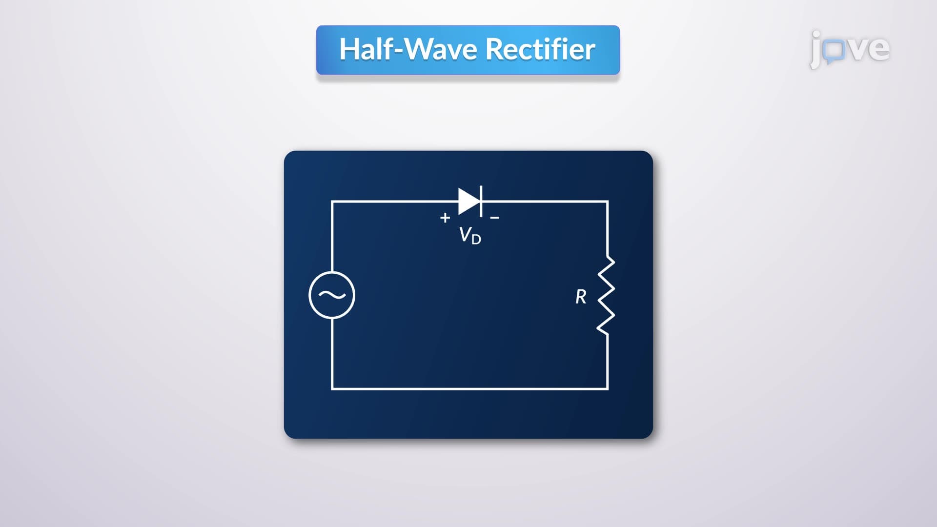
A full wave rectifier represents a fundamental power electronics circuit that converts alternating current (AC) input into direct current (DC) output by utilizing both half-cycles of the input waveform. While the transcript focuses on center-tapped configurations, understanding the broader bridge rectifier concept is crucial for modern electronics applications.
The bridge rectifier definition encompasses a four-diode arrangement forming a diamond or bridge configuration that eliminates the center-tapped transformer requirement. This design innovation, developed in the mid-20th century, revolutionized power supply design by reducing transformer size and cost while improving efficiency.
What is bridge rectifier in detail involves understanding its sophisticated yet elegant operation. During the positive half-cycle, diagonally opposite diodes (typically D1 and D4) conduct while the other pair remains reverse-biased. Current flows through the load resistor in one direction. During the negative half-cycle, the alternate diagonal pair (D2 and D3) conducts, maintaining current flow in the same direction through the load.
This bridge rectifier concept achieves several advantages over center-tapped designs. The peak inverse voltage across each diode equals the peak input voltage (rather than twice the peak voltage in center-tapped circuits), allowing use of lower-voltage-rated diodes. Additionally, the transformer utilization factor improves significantly since both halves of the secondary winding contribute to power delivery during each half-cycle.
Modern bridge rectifier basics extend far beyond simple power supplies. In the United States, automotive alternators employ three-phase bridge rectifiers to convert mechanical energy into electrical power for vehicle systems. Similarly, welding equipment, uninterruptible power supplies (UPS), and electric vehicle charging infrastructure all rely on sophisticated bridge rectifier designs.
The efficiency advantages make bridge rectifiers essential in energy-conscious applications. While half-wave rectifiers achieve only 40.6% efficiency, full-wave bridge rectifiers can exceed 81% efficiency under optimal conditions. This performance difference translates to significant energy savings in large-scale applications like data centers and manufacturing facilities.
Students preparing for AP Physics, college circuit analysis courses, or engineering fundamentals will encounter bridge rectifiers in both theoretical and practical contexts. Understanding ripple factor calculations, filter capacitor sizing, and voltage regulation becomes crucial for comprehensive mastery.
The bridge rectifier study guide should emphasize mathematical relationships: output voltage equals approximately 0.636 times the peak input voltage (accounting for diode voltage drops), and the ripple frequency doubles the input frequency. These relationships frequently appear in engineering problem sets and standardized assessments.
Related Micro-courses