Loading…
Loading video…

2,559 views
Why can your smartphone charger safely convert 120V wall power to just 5V without catching fire? Equivalent circuits for practical transformers make this everyday miracle possible through electromagnetic principles discovered over 150 years ago. The ideal transformer represents the theoretical foundation underlying every power adapter, electrical grid transformer, and voltage converter from California's Pacific Gas & Electric substations to your home electronics. Watch the full video on JoVE Coach to master this concept with expert-led visuals and step-by-step explanations.
The ideal transformer represents a theoretical electrical device that perfectly transfers electrical energy between circuits through electromagnetic induction, without any losses. This foundational concept helps engineering students understand real transformers used throughout America's electrical infrastructure, from massive utility transformers at Hoover Dam to tiny transformers inside LED light bulbs.
Two fundamental laws govern transformer behavior. Faraday's law explains how changing magnetic flux induces voltage across windings, creating the voltage transformation effect. When alternating current flows through the primary winding, it generates a time-varying magnetic field that links with the secondary winding, inducing voltage proportional to the rate of flux change and number of turns.
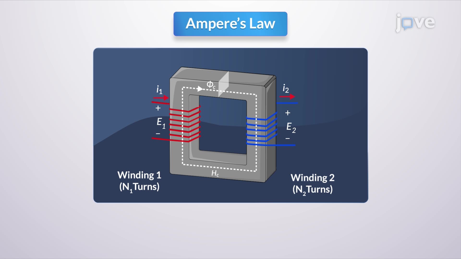
Ampere's law describes how current creates magnetic field intensity around conductors. In transformers, this law helps determine the magnetomotive force balance between windings. The total magnetomotive force around the magnetic circuit must equal zero in steady-state operation, establishing the current transformation relationship.
The transformer's magnetic core provides a low-reluctance path for magnetic flux, similar to how copper wires provide low-resistance paths for electric current. Core reluctance depends on core geometry, cross-sectional area, and magnetic permeability. For ideal transformers, infinite core permeability creates zero reluctance, meaning no magnetomotive force is required to establish core flux.
This idealization eliminates magnetizing current requirements and ensures all flux remains confined within the core, linking both windings perfectly. Real transformers approach this ideal using high-permeability materials like silicon steel or ferrite cores.
Understanding ideal transformer theory proves essential for AP Physics students analyzing circuit problems and electrical engineering undergraduates studying power systems. The SAT Physics Subject Test frequently includes transformer problems requiring turns ratio calculations and power balance analysis.
Real applications include distribution transformers reducing 13.8 kV neighborhood power to 240V/120V household voltage, isolation transformers in medical equipment ensuring patient safety, and step-up transformers at power plants increasing generator voltage for efficient long-distance transmission across America's electrical grid.
Frequently Asked Questions
An ideal transformer is a theoretical device with infinite core permeability, zero losses, and perfect coupling between windings. Real transformers have finite permeability, resistance losses, and leakage flux, but ideal transformer analysis provides accurate approximations for most practical applications.
AP Physics C and college circuits exams frequently test turns ratio calculations, power conservation, and impedance transformation. Typical problems involve finding secondary voltage given primary voltage and turns ratio, or calculating reflected impedance in coupled circuits.
Master the turns ratio equation V1/V2 = N1/N2, current relationship I1/I2 = N2/N1, and power conservation P1 = P2. These three relationships solve most exam problems involving ideal transformers in physics and engineering coursework.
Ideal transformer analysis provides 95-98% accuracy for most power transformers, making complex calculations manageable while teaching fundamental electromagnetic principles. Engineers then add loss corrections for precise design work.
Smartphone chargers use switching transformers operating at high frequencies (typically 50-100 kHz) with ferrite cores approaching ideal behavior. The 120V to 5V transformation follows ideal transformer principles, with additional circuitry handling AC-to-DC conversion.
Basic trigonometry, complex numbers for AC analysis, and introductory calculus for understanding Faraday's law suffice for most undergraduate applications. High school algebra handles turns ratio calculations and power balance problems on standardized tests.
Progress to practical transformer equivalent circuits, three-phase transformers, autotransformers, and magnetic circuit analysis. These topics build directly on ideal transformer foundations while adding real-world complexity for advanced engineering applications.
Start with the turns ratio to find unknown voltages or currents, then apply power conservation to check answers. Draw simple circuit diagrams showing primary and secondary sides, and always verify that power in equals power out for ideal operation.
Related Micro-courses

Related Subjects
 Civil Engineering 30 micro-courses›Mechanical Engineering 28 micro-courses›