Loading subject page…


13 Concepts
11 Concepts
9 Concepts
8 Concepts
13 Concepts
16 Concepts
9 Concepts
11 Concepts
15 Concepts
11 Concepts
14 Concepts
20 Concepts
11 Concepts
7 Concepts
5 Concepts
7 Concepts
10 Concepts
7 Concepts
7 Concepts
5 Concepts
9 Concepts
7 Concepts
7 Concepts
7 Concepts
10 Concepts
4 Concepts
7 Concepts
6 Concepts
8 Concepts
9 Concepts
7 Concepts
5 Concepts
5 Concepts
 8 Concepts
 1.9K Views
 Popular topics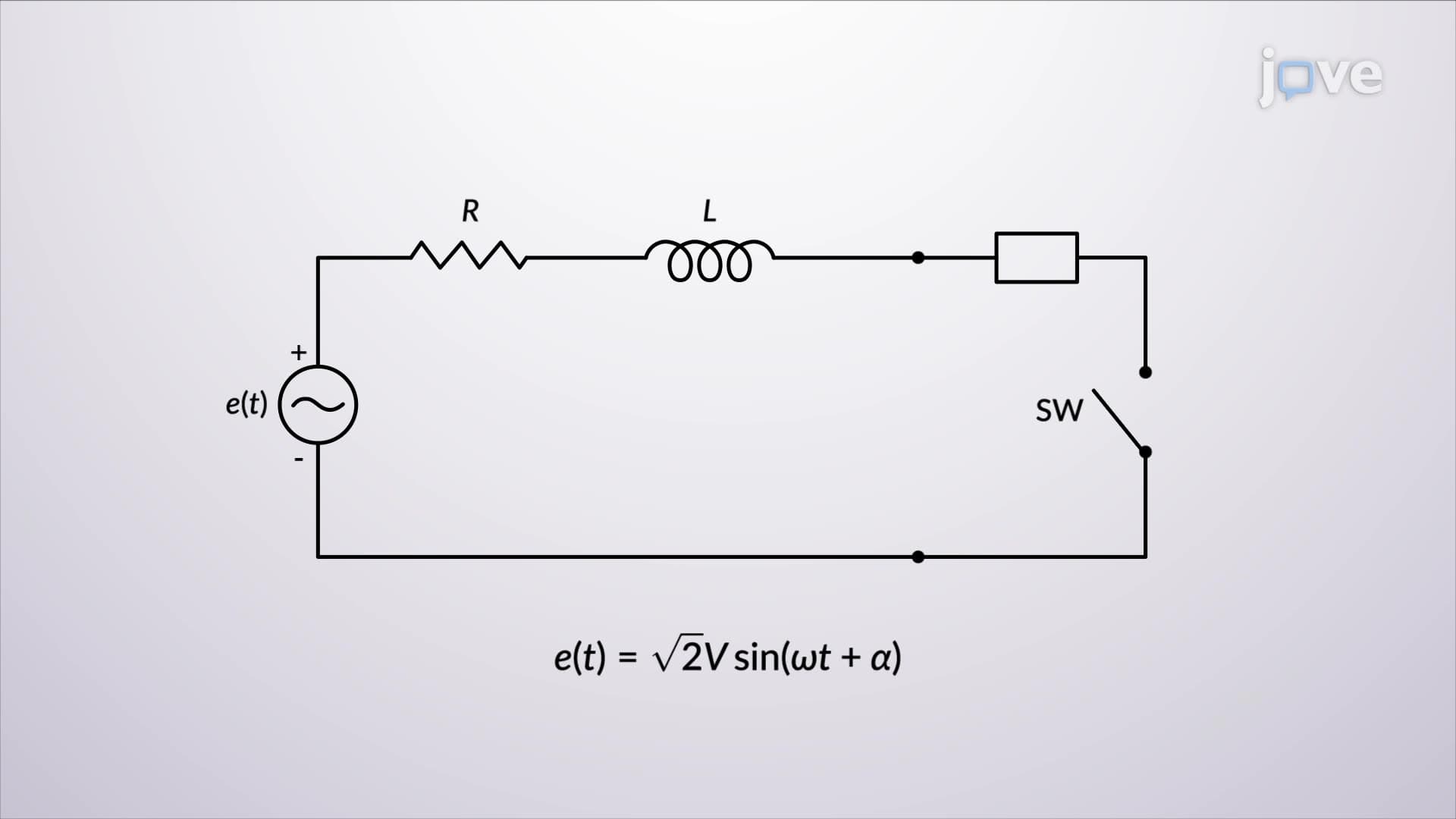




Symmetrical and unsymmetrical faults represent critical disturbances in electrical power systems that require comprehensive analysis for safe operation. This JoVE Coach micro-course explores short circuit fault analysis techniques, examining three-phase fault behavior, sequence components theory, and practical applications in US power grids, from generation facilities to distribution networks.
1. Series R-L Circuit Transient Analysis: Understanding fault current behavior through series resistance-inductance circuits provides the foundation for analyzing more complex power system faults. When a switch closes in an R-L circuit, it mimics three-phase short circuit conditions in synchronous machines. The total fault current comprises two components: an AC symmetrical component that maintains steady-state sinusoidal behavior, and a DC offset component that decays exponentially with time constant L/R. The maximum asymmetrical current occurs at specific source angles, with the RMS value determined by multiplying the AC fault current by an asymmetry factor. Higher reactance-to-resistance ratios produce larger fault currents, making this analysis crucial for protective equipment sizing in US power systems.
2. Three-Phase Short Circuit in Synchronous Machines: Unloaded synchronous machine behavior during short circuits reveals fundamental power system dynamics essential for fault analysis. The AC fault current oscillogram shows decreasing amplitude from initial high values to steady-state conditions, caused by magnetic flux redistribution from high-reluctance to low-reluctance paths. Standard machine theory provides subtransient, transient, and synchronous reactances that determine fault current magnitude at different time intervals. Each phase experiences different DC offset components, with maximum offset occurring at specific phase angles. Machine manufacturers provide reactance values and time constants that enable engineers to predict system behavior during faults, ensuring proper protection coordination in facilities like those operated by Tennessee Valley Authority or Pacific Gas & Electric.
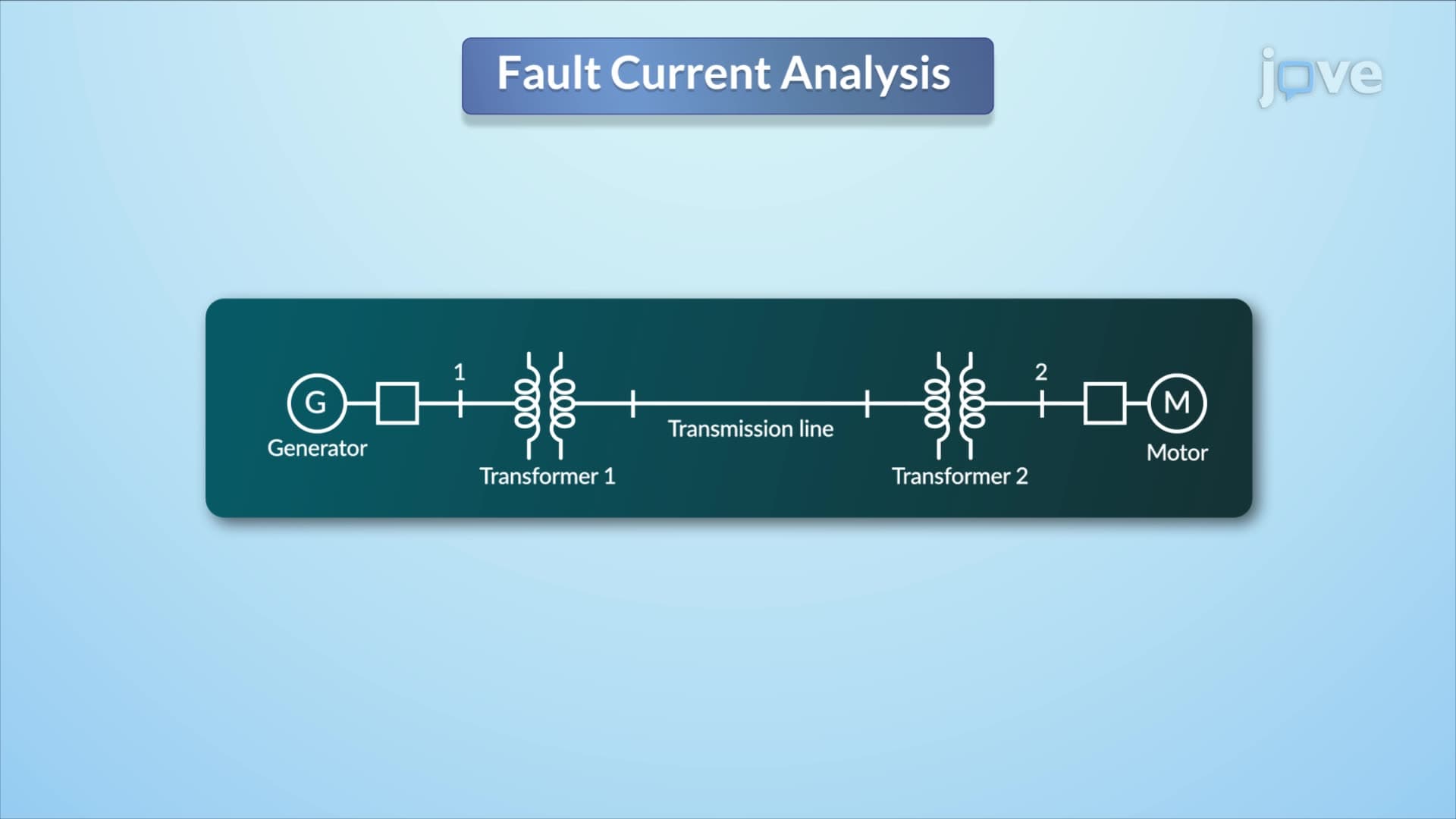
3. Power System Fault Current Calculation Methods: Comprehensive fault analysis requires systematic approaches for calculating currents in complex interconnected systems. Transformers are modeled using leakage reactances, transmission lines by equivalent series reactances, and synchronous machines as voltage sources behind subtransient reactances. The analysis typically neglects resistances, shunt admittances, and loads under 50 horsepower for simplification. Superposition principles enable fault current calculation by analyzing pre-fault and fault conditions separately. Single-line diagrams represent three-phase systems efficiently, while positive-sequence equivalent circuits model balanced fault conditions. This methodology forms the basis for protection system design in major US utilities and industrial facilities.
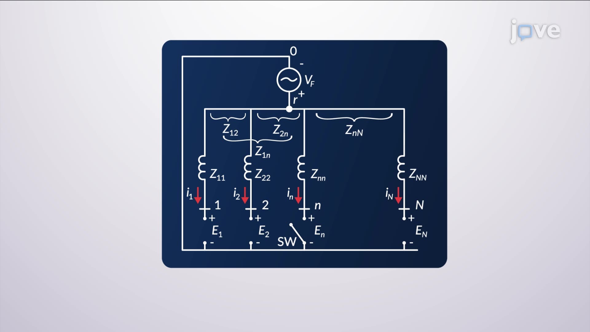
4. Bus Impedance Matrix Applications: Multi-bus power system analysis utilizes the bus impedance matrix method for determining fault currents and voltages throughout the network. The positive-sequence bus admittance matrix transforms to the impedance matrix through mathematical inversion, enabling direct calculation of fault effects. When a three-phase fault occurs at any bus, the analysis involves two circuits solved using superposition: one representing the fault condition with machine sources short-circuited, and another representing pre-fault steady-state conditions. Self-impedances and mutual impedances determine current distribution during faults. This method proves invaluable for analyzing large interconnected systems like the Eastern Interconnection or Western Electricity Coordinating Council networks.
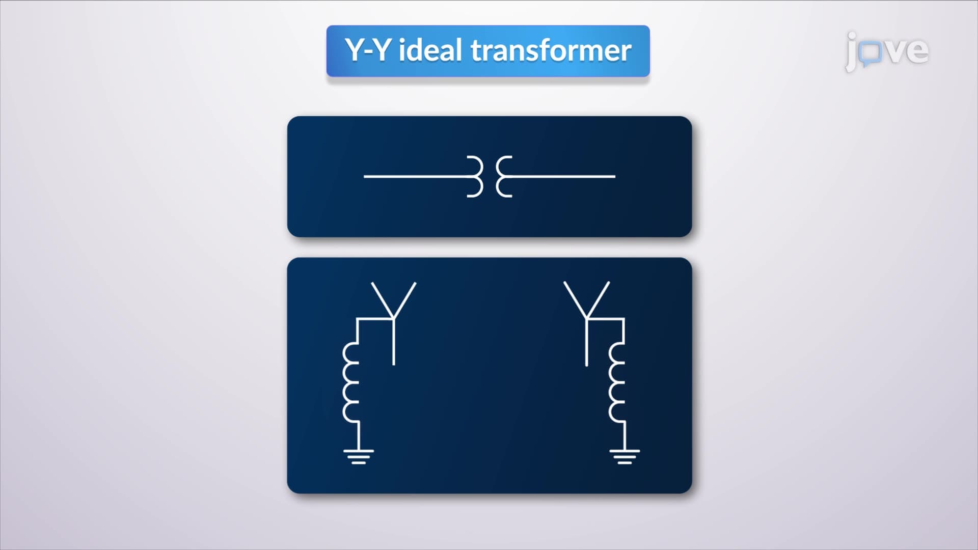
5. Sequence Network Theory and Components: Symmetrical components theory transforms unbalanced three-phase systems into balanced sequence networks for simplified analysis. Zero-sequence components represent identical currents in all phases, positive-sequence represents normal balanced operation, and negative-sequence represents reverse rotation effects. Each sequence network contains specific impedance values: synchronous machines typically exhibit lowest zero-sequence impedance due to minimal net magnetomotive force from identical phase currents. Transformers and transmission lines have identical positive and negative sequence impedances, while zero-sequence impedances depend on grounding configurations. Y-connected generators require neutral impedance consideration, while delta connections prevent zero-sequence current flow. Understanding sequence networks enables analysis of unsymmetrical faults common in overhead transmission systems across the continental United States.
6. Circuit Breaker and Protective Device Selection: Proper selection of circuit breakers and fuses requires understanding fault current magnitudes and system characteristics to ensure safe interruption capability. Circuit breakers extinguish arcs through elongation and cooling mechanisms, with classifications based on voltage levels and arc-extinguishing media. High-voltage breakers incorporate automatic reclosing features, operating 15-50 cycles after initial tripping to clear temporary faults common on overhead lines. Low-voltage molded-case breakers use magnetic trips for large fault currents and thermal trips for sustained overloads. The E/X method simplifies breaker selection by calculating maximum symmetrical short-circuit current using pre-fault voltage divided by system reactance. Generator protection requires two-cycle breakers selected based on subtransient fault currents, while motor protection may use either subtransient or transient reactances depending on breaker speed requirements.