Loading subject page…


1,385 views

Video Summary: Design of Prismatic Beams for Bending Explained
Ever wondered how engineers ensure that the steel beams supporting your school's gymnasium won't collapse under load? The design of prismatic beams for bending is a critical engineering process that determines the safe dimensions and materials for structural components. From the I-beams in Manhattan skyscrapers to the wooden joists in residential homes across America, this systematic approach prevents catastrophic failures by calculating allowable stresses, analyzing bending moments, and selecting appropriate cross-sectional properties. Watch the full video on JoVE Coach to master this concept with expert-led visuals and step-by-step explanations.
The design of prismatic beams for bending represents a fundamental aspect of structural engineering that ensures buildings, bridges, and other structures can safely support their intended loads. This systematic approach combines material science principles with mathematical analysis to prevent structural failures that could endanger lives and property. In the United States, this process follows established codes such as the American Institute of Steel Construction (AISC) standards and the National Design Specification (NDS) for wood construction.
The foundation of beam design begins with understanding material properties and establishing appropriate safety factors. Engineers consult standardized references like the Steel Construction Manual or the Wood Handbook published by the US Forest Products Laboratory to determine ultimate strength values. The allowable stress is calculated by dividing the material's ultimate strength by a safety factor, typically ranging from 1.5 to 3.0 depending on the application and loading conditions. For example, structural steel used in commercial buildings might have an ultimate tensile strength of 65,000 psi, with an allowable stress of approximately 22,000 psi when applying a safety factor of 2.5.
The next phase involves creating shear force and bending moment diagrams that graphically represent how loads affect the beam throughout its length. These diagrams help identify the location and magnitude of maximum bending moments, which typically occur at points of maximum loading or support reactions. For instance, in a simply supported beam carrying a uniform load (like snow on a roof), the maximum bending moment occurs at the center span and equals WL²/8, where W represents the total load and L is the span length.
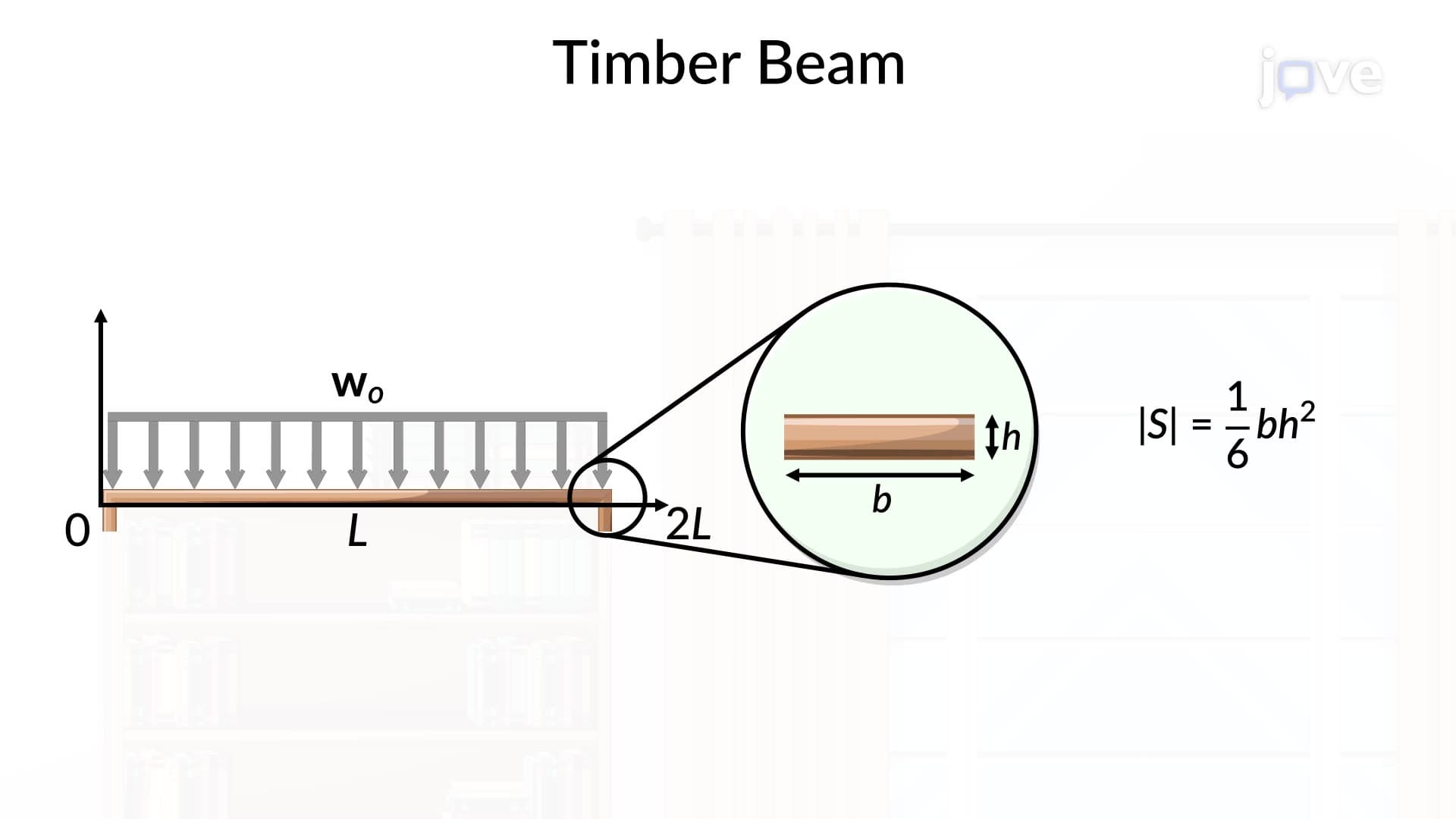
The section modulus calculation forms the core of beam sizing, relating the maximum bending moment to allowable stress through the formula: Section Modulus = Maximum Bending Moment / Allowable Stress. For timber beams, engineers often work with predetermined width-to-depth ratios (commonly 2:1 or 3:1) that reflect standard lumber dimensions and optimize material usage. Steel beam design, however, involves selecting from standardized shapes like W-sections (wide flanges) or S-sections (standard I-beams) using comprehensive property tables that list section modulus values for various beam sizes. This difference reflects the manufacturing processes and economic considerations unique to each material type.
Students preparing for AP Physics, college-level statics courses, or engineering programs will encounter these principles in problem-solving contexts that require both conceptual understanding and computational skills. The systematic approach emphasizes the importance of safety in engineering design while providing practical tools for real-world applications.
Related Micro-courses