Loading subject page…

- Mechanical Engineering
- Principal Stresses Under a Given Loading
- Transmission Shafts: Problem Solving
Micro-course: Principal Stresses under a Given Loading
1,707 views
Learn key concepts and earn your certificate.



Transmission Shafts: Problem Solving


00:00
01:09
Video Summary: What Is Transmission Shafts Problem Solving
Ever wonder how the Boeing 787's massive engines transfer power to aircraft systems without the shaft snapping under immense torque? Transmission shafts problem solving involves calculating the minimum diameter needed for solid shafts to safely transmit power from motors to machinery, like those used in Ford's automotive assembly lines. This engineering process requires analyzing torque, bending moments, and shearing stress to prevent catastrophic mechanical failures. Watch the full video on JoVE Coach to master this concept with expert-led visuals and step-by-step explanations.
- Understand what is transmission shafts problem solving and its critical role in mechanical system design
- Identify the key variables needed to calculate minimum shaft diameter, including power, rotational speed, and allowable shearing stress
- Analyze torque calculations using power transmission values and shaft revolution data
- Apply bending moment diagram techniques to determine forces acting on horizontal and vertical planes
- Evaluate critical transverse sections by calculating the square root of sum of squares for bending moments and torsion
- Recognize how polar moment ratios relate shearing stress to geometric shaft properties
- Compare different shaft loading scenarios and their impact on diameter requirements
- Explore real-world applications in automotive, aerospace, and industrial machinery design
Understanding Transmission Shafts Problem Solving Fundamentals
Transmission shafts problem solving represents a cornerstone of mechanical engineering design, focusing on determining the minimum safe diameter for rotating shafts that transmit power between mechanical components. This process is essential for ensuring that shafts in everything from Tesla Model 3 drivetrains to Caterpillar excavator hydraulic systems can handle operational loads without failure.
Power Transmission and Torque Calculations
The foundation of transmission shafts problem solving begins with understanding the relationship between power, rotational speed, and torque. Engineers use the fundamental equation: Power = Torque × Angular Velocity. For instance, when designing the drivetrain for a John Deere combine harvester, engineers must calculate the exact torque requirements based on the engine's power output and the desired rotational speed of the threshing mechanism.
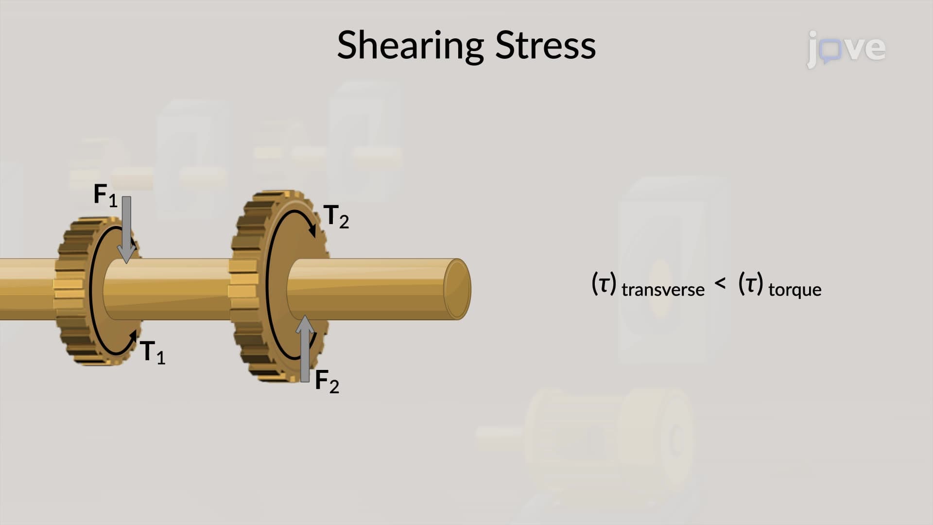
This calculation becomes critical in AP Physics C courses and college-level Statics and Dynamics classes, where students learn that torque directly influences the shearing stress within the shaft material. The tangential forces acting on connected gears are computed from this torque value, establishing the foundation for all subsequent stress analysis.
Bending Moment Analysis and Critical Sections
Advanced transmission shafts problem solving requires creating bending moment diagrams that account for forces acting in multiple planes. Engineers must consider both horizontal and vertical force components, particularly in complex machinery like those found in Boeing's aircraft manufacturing facilities. These diagrams reveal critical transverse sections where maximum stress concentrations occur.
The mathematical approach involves calculating the square root of the sum of squares of bending moments and torsional loads at each critical section. This vector combination technique, commonly taught in college Mechanics of Materials courses and tested on the Fundamentals of Engineering (FE) exam, ensures that engineers account for the complex three-dimensional stress states that real shafts experience.
Polar Moment of Inertia and Safety Factor Integration
The final step in transmission shafts problem solving involves applying the polar moment of inertia relationship to determine minimum shaft radius. This calculation connects material properties (allowable shearing stress) with geometric requirements (shaft diameter) and loading conditions (combined bending and torsion). Students preparing for mechanical engineering licensing exams must master this integration of theoretical principles with practical design constraints, ensuring that shafts in critical applications like SpaceX rocket engine turbopumps maintain adequate safety margins while minimizing weight and material costs.
Frequently Asked Questions
Transmission shafts problem solving is the systematic process of calculating the minimum safe diameter for rotating shafts that transmit power between mechanical components. This engineering discipline prevents catastrophic failures in critical systems like aircraft engines, automotive drivetrains, and industrial machinery. It combines material science, mechanics principles, and safety engineering to ensure reliable power transmission while optimizing material usage and cost-effectiveness.
These problems commonly appear as multi-step calculations involving torque, bending moments, and stress analysis on AP Physics C Mechanics exams and college Statics/Dynamics midterms. Students typically receive power transmission data and must work through torque calculations, bending moment diagrams, and polar moment relationships. The FE exam frequently includes shaft design problems requiring integration of multiple mechanical engineering principles within time constraints.
Success requires solid understanding of trigonometry for force component analysis, calculus for moment calculations, and vector mathematics for combining bending and torsional loads. Students should be comfortable with algebraic manipulation of engineering formulas and unit conversions. College-level courses typically assume proficiency in these areas, while AP Physics C provides introductory exposure to these mathematical applications in mechanical systems.
Ford engineers use these principles to design transmission shafts that handle engine torque in F-150 trucks, while Boeing applies them to aircraft engine accessory drives and control system actuators. Tesla's engineers optimize electric motor drive shafts using these calculations to maximize efficiency while ensuring safety. These real-world applications require consideration of fatigue loading, temperature effects, and manufacturing tolerances beyond basic textbook problems.
Students often struggle with visualizing three-dimensional force systems and understanding how bending moments combine with torsional loads. The mathematical complexity of polar moment calculations and the integration of multiple stress types can be overwhelming initially. However, starting with simple solid shafts and gradually building complexity helps students develop intuitive understanding before tackling advanced applications with hollow shafts or complex loading patterns.
Practice with progressively complex problems, starting with pure torsion cases before adding bending loads, helps build conceptual understanding. Create summary sheets linking equations to physical meanings, and work through complete design problems rather than isolated calculations. Form study groups to discuss different solution approaches, and use online engineering calculators to verify hand calculations while learning the underlying principles.
Advanced studies include fatigue analysis for cyclic loading, hollow shaft optimization, critical speed calculations for high-RPM applications, and temperature effects on material properties. Students can explore finite element analysis techniques, composite shaft design, and advanced manufacturing considerations. These topics appear in graduate-level mechanical engineering courses and professional practice in industries like renewable energy and advanced manufacturing.
While not directly tested, the problem-solving methodology and physics principles strengthen analytical thinking skills valuable for MCAT Physical Sciences passages. The mathematical reasoning and systematic approach to complex problems translates well to biochemical pathway analysis and physics problem-solving strategies. Understanding mechanical systems also provides background knowledge for biomechanics concepts that occasionally appear in MCAT biological sciences sections.
Related Micro-courses


