Loading video…


 4 Concepts
 2.6K views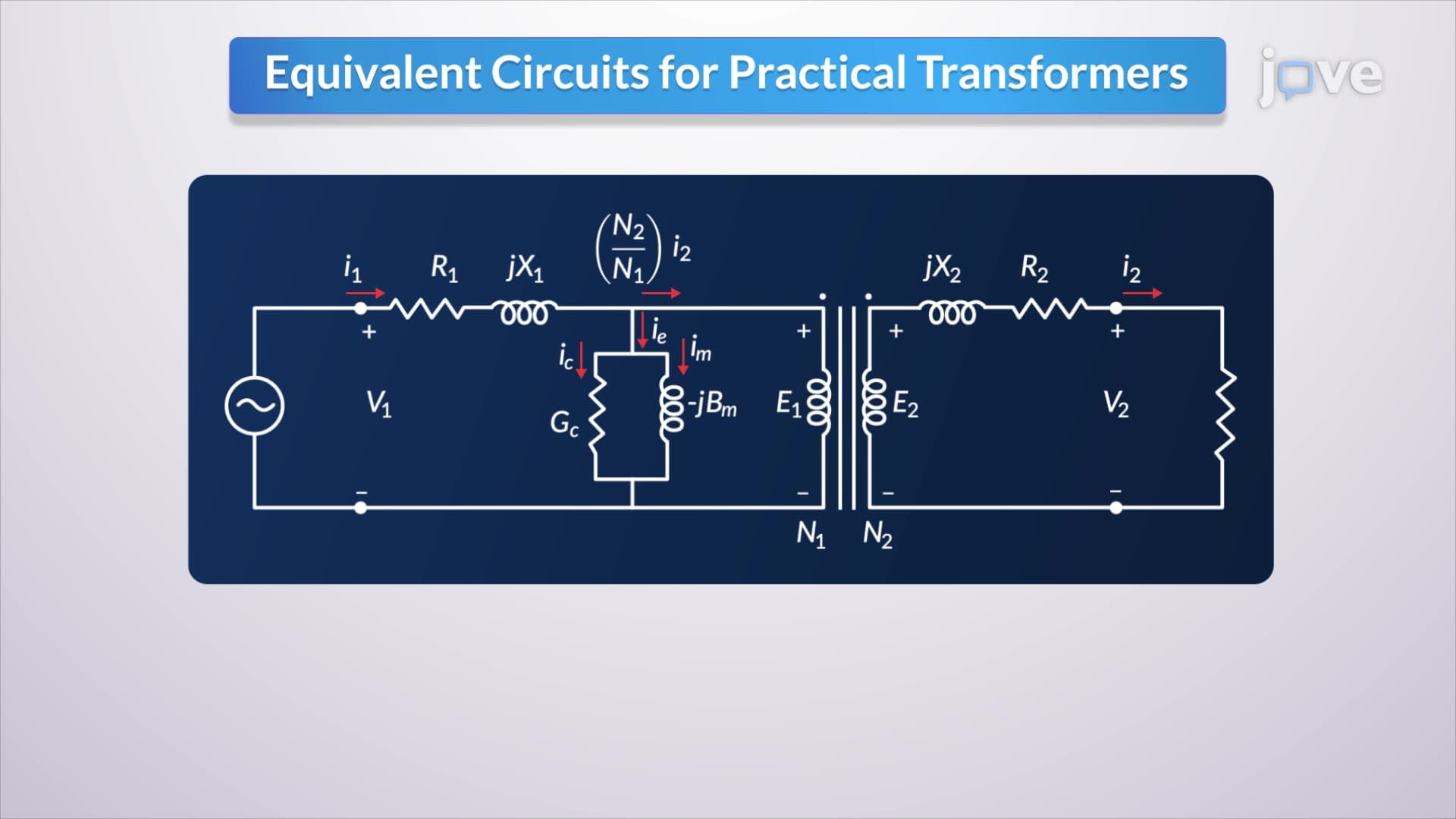

Video Summary: Equivalent Circuits for Practical Transformers Explained
Ever wondered why power grids across the United States use three winding transformers instead of simpler designs? These sophisticated electrical components handle voltage conversion at different levels simultaneously, making them essential for efficiently distributing electricity from power plants in Texas to homes in California. Understanding Equivalent Circuits For Practical Transformers Explained reveals how real transformers differ from idealized models due to resistance losses, magnetic flux leakage, and core permeability limitations that affect power transmission efficiency. Watch the full video on JoVE Coach to master this concept with expert-led visuals and step-by-step explanations.
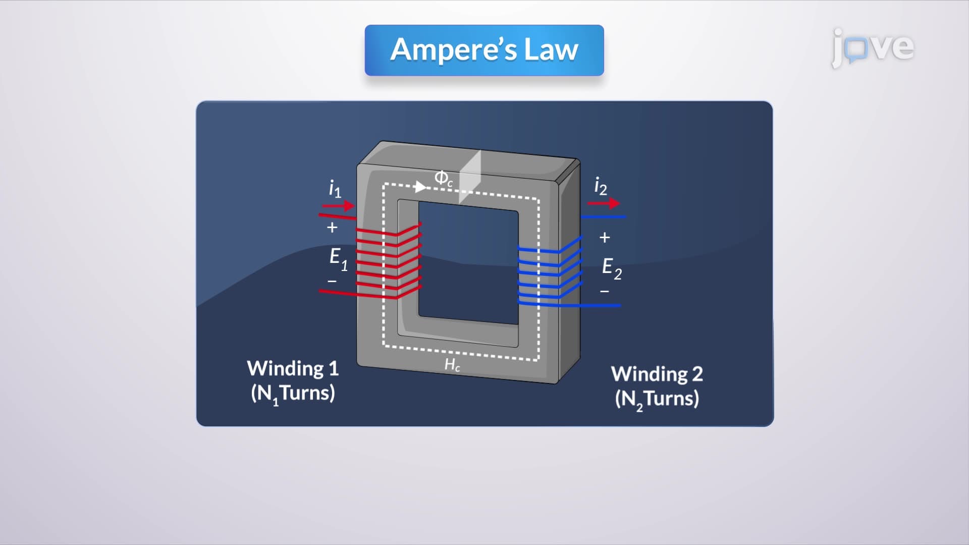
Real transformers in electrical power systems deviate significantly from the idealized models taught in introductory physics courses. While ideal transformers assume perfect coupling and zero losses, practical transformers exhibit measurable resistance, leakage inductance, and core losses that engineers must account for in circuit analysis and design.
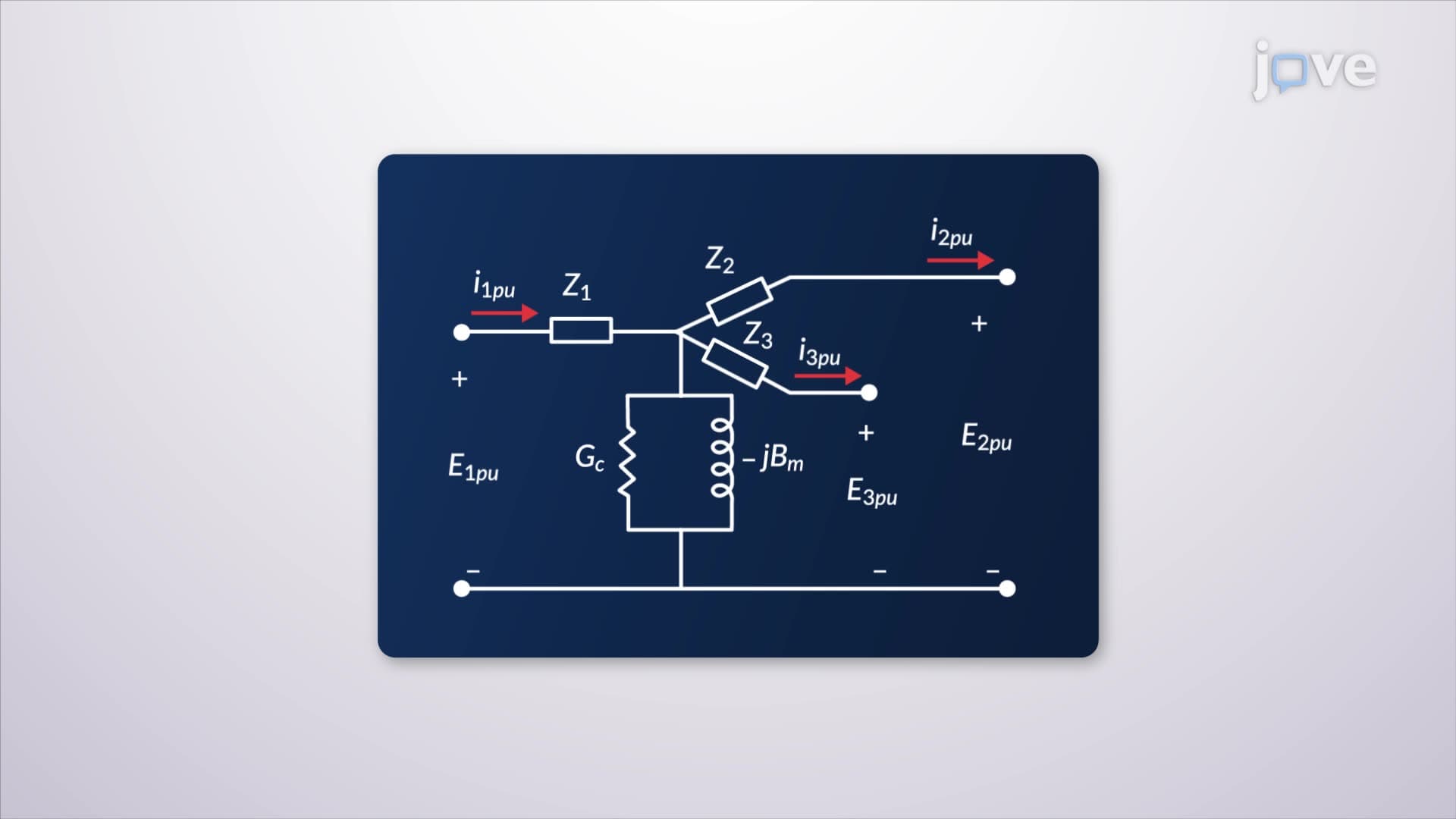
Three winding transformers serve critical roles in electrical distribution networks, particularly in substations where multiple voltage levels must be managed simultaneously. Unlike two-winding transformers that convert between two voltage levels, types of three winding transformers include autotransformers, isolation transformers, and distribution transformers that can step voltage up or down while providing additional outputs. For example, utility companies in states like California use three-winding transformers at distribution substations to convert high-voltage transmission lines (115 kV) down to both medium voltage (12 kV) for commercial districts and low voltage (480V) for residential areas.
The equivalent circuit representation incorporates several parasitic elements that cause energy dissipation. Winding resistance appears in series with each coil, representing I²R losses from current flow through copper conductors. Leakage reactance accounts for magnetic flux that doesn't link both windings completely, creating voltage drops proportional to load current. These concepts frequently appear on AP Physics C exams and college-level electrical engineering coursework.
What are three winding transformers overview reveals their complex magnetic behavior through equivalent circuit analysis. The magnetizing branch includes a shunt inductor representing the magnetizing current required to establish magnetic flux in the core. This current lags the applied voltage by 90 degrees, consuming reactive power. Additionally, a parallel resistor models core losses from hysteresis and eddy currents in the magnetic material. Students preparing for the MCAT or engineering fundamentals exams should understand that minimizing these losses requires high-permeability, low-loss magnetic materials like silicon steel or amorphous metal alloys used in modern US power grid transformers.
Related Micro-courses