Loading video…


 4 Concepts
 2.6K views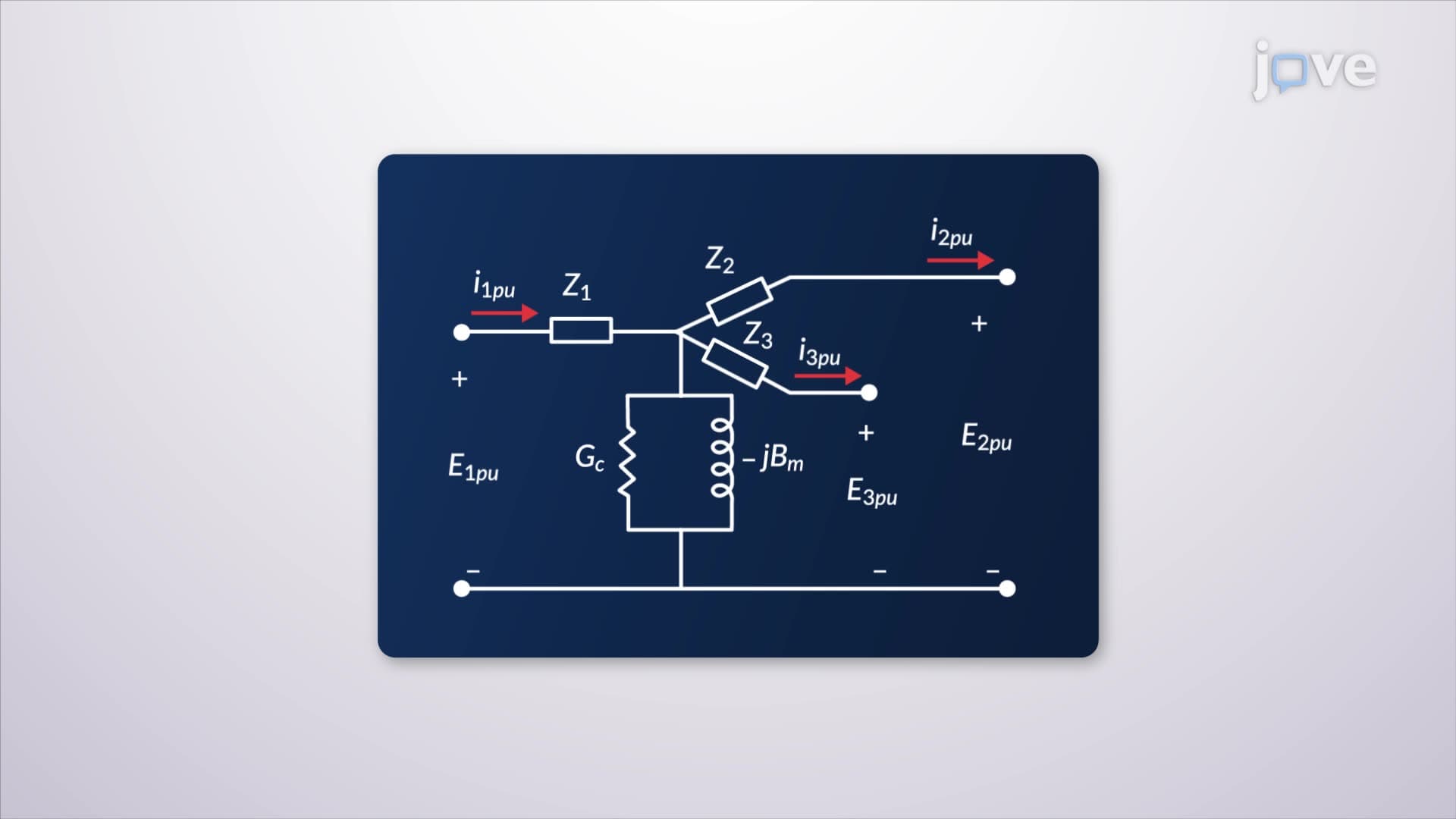

Video Summary: What are Three Winding Transformers
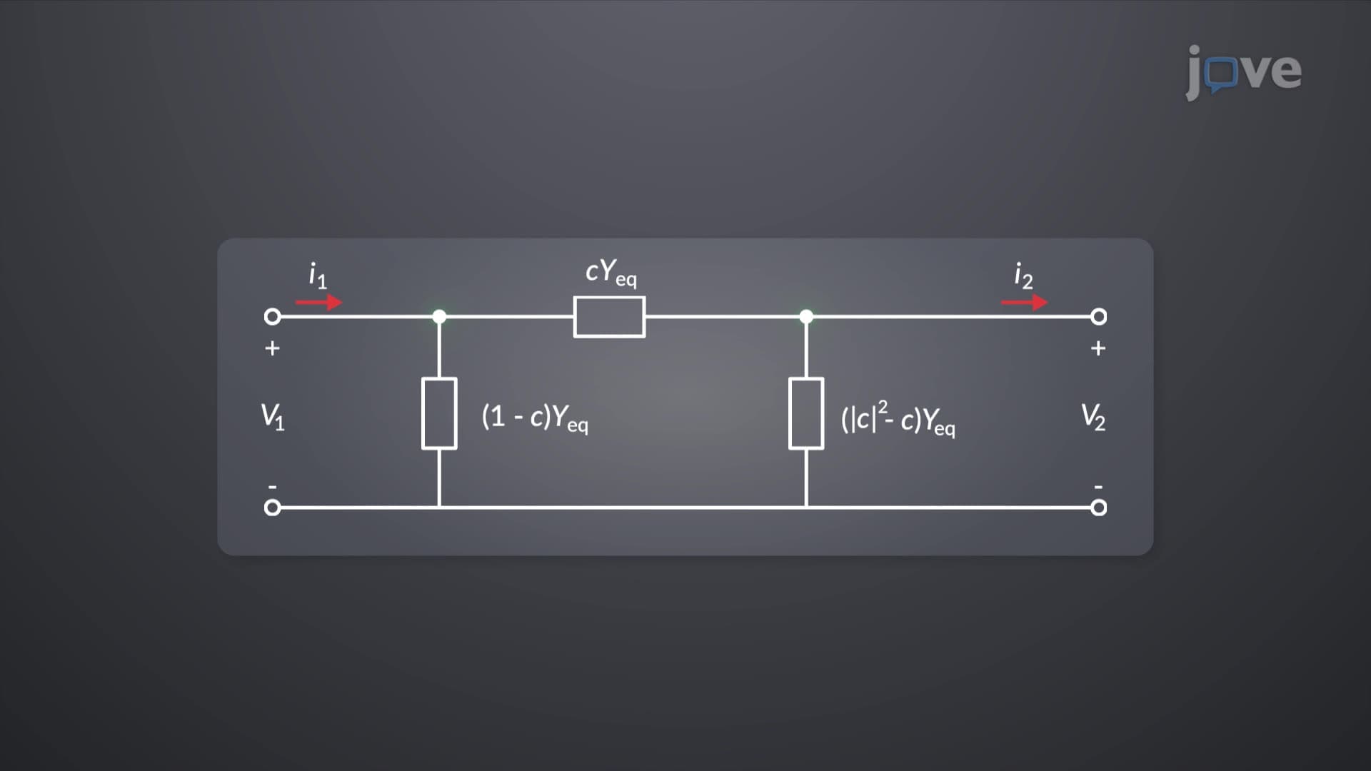
Ever wondered how power companies manage complex electrical distribution across multiple voltage levels simultaneously? Transformers with off nominal turns ratios enable precise voltage regulation in three-winding configurations, where a single transformer handles primary, secondary, and tertiary circuits-like those powering industrial facilities, residential neighborhoods, and emergency systems in places like Con Edison's Manhattan grid. What are Three Winding Transformers reveals how these sophisticated devices maintain power quality across multiple outputs. Watch the full video on JoVE Coach to master this concept with expert-led visuals and step-by-step explanations.
Three-winding transformers represent a sophisticated evolution beyond basic two-winding designs, featuring primary, secondary, and tertiary windings on a common magnetic core. These transformers with off nominal turns ratios enable simultaneous voltage transformation to multiple levels, making them essential for complex power distribution networks. Unlike simple step-up or step-down transformers, three-winding units can simultaneously supply different voltage requirements-for example, stepping down from 138 kV transmission voltage to both 13.8 kV distribution and 480V industrial levels.
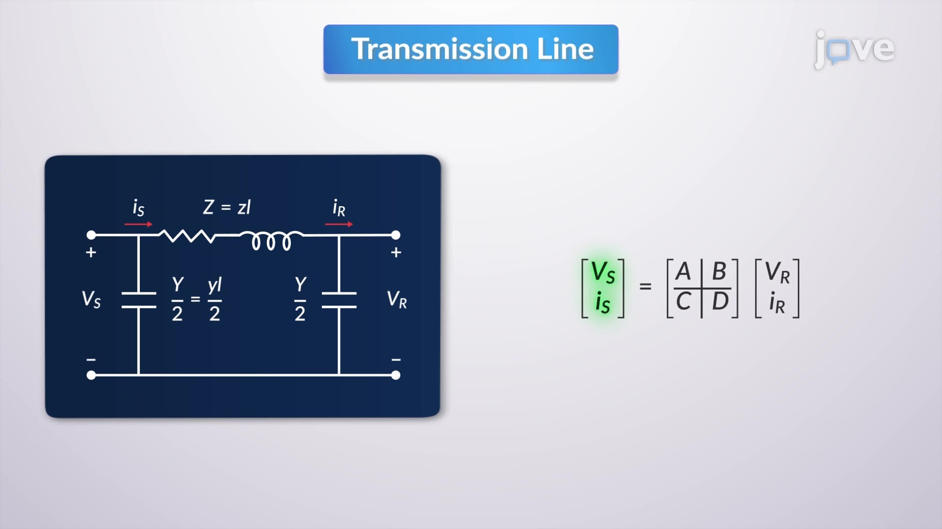
The mathematical analysis of transformers with off nominal turns ratios tutorial involves sophisticated per-unit calculations that normalize different voltage and power levels to common bases. Engineers establish base quantities using the transformer's rated complex power and voltage ratios matching line-to-line specifications. This per-unit system simplifies calculations by eliminating the need to track actual voltage levels, instead working with normalized values that reveal system behavior more clearly.
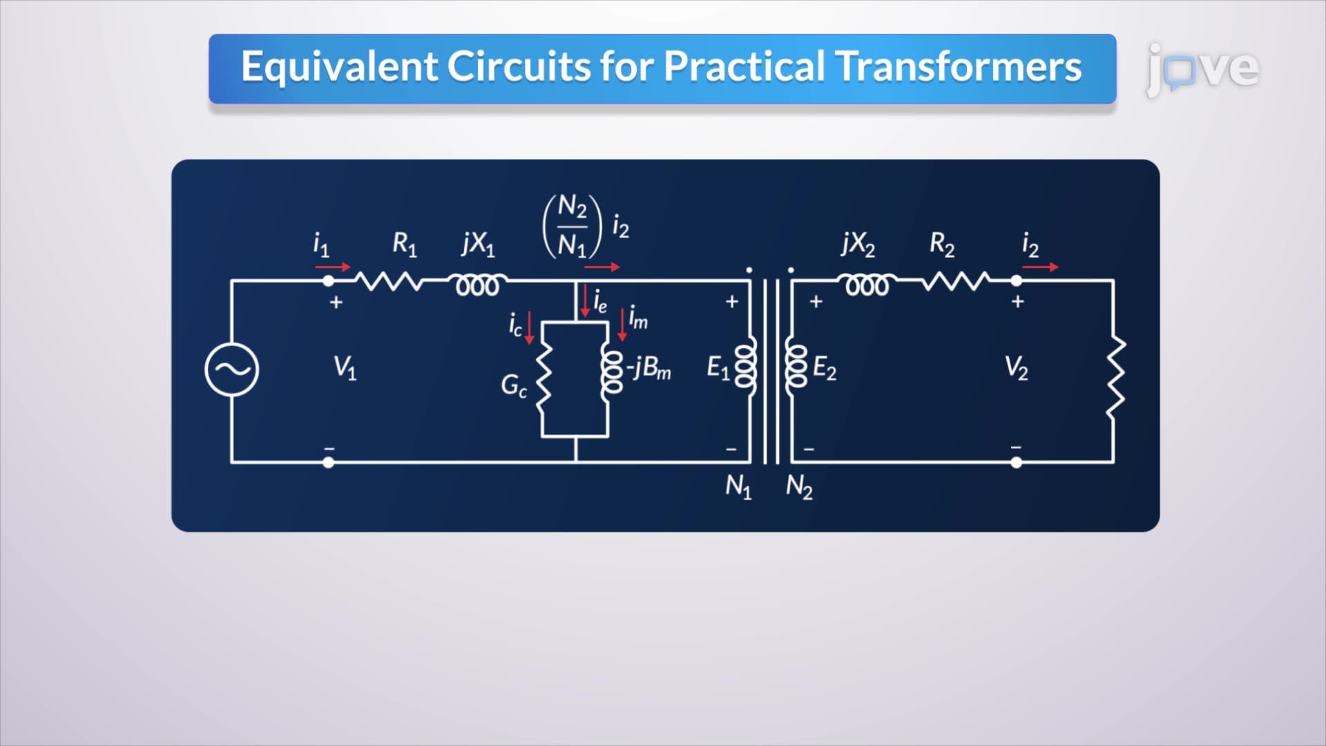
In grounded Y-Y configurations, balanced three-phase currents produce zero neutral current flow, significantly simplifying the equivalent circuit analysis. This characteristic makes the per-unit equivalent circuit remarkably similar to an ideal single-phase transformer, despite the complexity of the actual three-phase, three-winding physical system.
Understanding how transformers with off nominal turns ratios works requires comprehensive testing protocols that characterize transformer behavior under various operating conditions. Standard open-circuit tests determine shunt admittance branches by measuring no-load losses and magnetizing current with one winding energized and others open-circuited. These tests reveal core losses and magnetizing impedance values critical for accurate system modeling.
Short-circuit tests evaluate leakage impedances by applying reduced voltage to one winding while short-circuiting others, measuring the resulting current and power loss. These measurements provide the series impedance values needed for equivalent circuit construction. With one winding open, the three-winding transformer effectively becomes a two-winding unit, simplifying analysis while maintaining measurement accuracy.
Three-winding transformers excel in applications requiring multiple voltage levels from a single source. Major utilities like Pacific Gas & Electric use these units in substations serving industrial complexes, where 230 kV transmission voltage simultaneously supplies 69 kV sub-transmission and 12 kV distribution circuits. The tertiary winding often provides station service power or reactive power compensation.
Students preparing for AP Physics C or college-level electrical engineering courses encounter these concepts when studying power systems and electromagnetic induction. The mathematical relationships extend naturally from basic transformer principles, making this an excellent bridge topic between introductory electromagnetics and advanced power system analysis.
Related Micro-courses