Loading video…


 7 Concepts
 1.7K views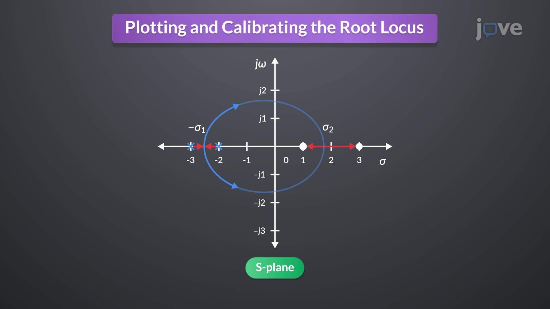

Video Summary: Plotting and Calibrating the Root Locus Explained
Ever wonder how NASA engineers ensure the Mars Perseverance rover maintains stable control during landing? Root loci for positive feedback systems reveal the critical boundaries where control systems shift from stable to unstable operation. Boeing's autopilot systems rely on these mathematical tools to predict exactly when increasing controller gain might cause dangerous oscillations or complete system failure. Plotting And Calibrating The Root Locus Explained demonstrates how engineers calculate breakaway points, analyze pole movements, and determine precise gain values that keep complex systems operating safely within design parameters. Watch the full video on JoVE Coach to master this concept with expert-led visuals and step-by-step explanations.
Root locus analysis serves as a fundamental graphical technique for understanding how closed-loop pole locations change as system parameters vary. Unlike negative feedback systems commonly studied in introductory control courses, positive feedback systems present unique challenges that require careful analysis of stability boundaries and gain relationships.
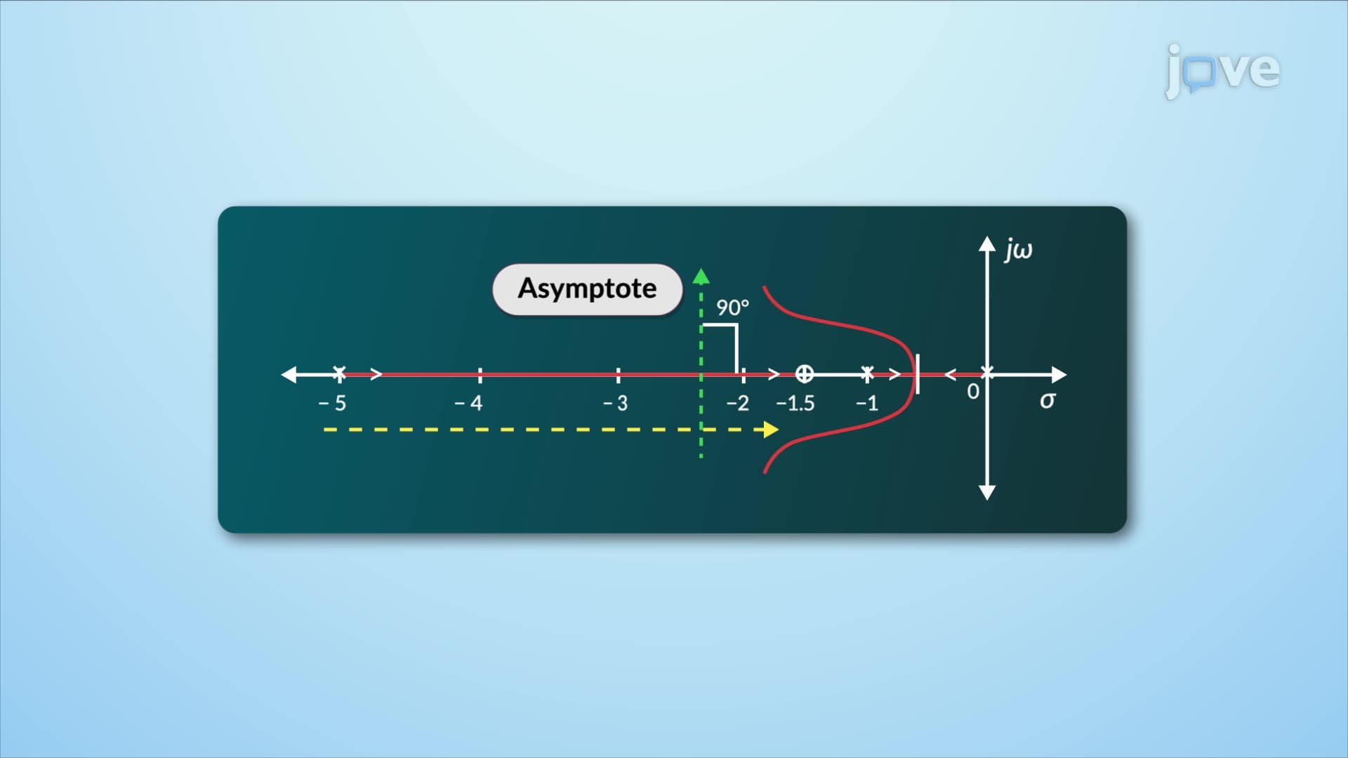
The critical transition points where root loci leave or rejoin the real axis deserve special attention in positive feedback analysis. Breakaway points occur between open-loop poles on the real axis, representing locations where maximum gain occurs before poles migrate into the complex plane. Conversely, break-in points appear between zeros, marking minimum gain locations where complex poles return to real axis behavior.
Consider a typical aircraft flight control system used in commercial aviation. Boeing 737 autopilot systems must account for these transition points when determining safe operating ranges for pitch control gains. Engineers calculate these points by finding where the derivative of the characteristic equation equals zero, ensuring the system maintains acceptable performance margins throughout the flight envelope.
The 180/n degree angular relationship governs where root loci can exist in the complex plane. For positive feedback systems, this criterion becomes particularly important when analyzing multi-loop control architectures common in industrial automation. General Electric's wind turbine control systems exemplify this principle, where blade pitch controllers must satisfy angular conditions to maintain stable power generation across varying wind speeds.
Students preparing for AP Physics C or college-level control systems courses should practice calculating these angles using graphical methods. The angular sum evaluation involves measuring angles from each pole and zero to test points along potential locus paths, verifying existence when the total equals an odd multiple of 180 degrees.
The magnitude condition provides the mathematical foundation for determining exact gain values at any point along the root locus. This calculation involves dividing the product of distances from all zeros by the product of distances from all poles to the point of interest. Tesla's Autopilot system utilizes similar calculations to determine optimal control gains that maintain vehicle stability while responding to steering inputs and road conditions.
For students tackling midterm exams in engineering programs like those at MIT or Stanford, mastering these calculations proves essential. Practice problems typically involve complex conjugate pole pairs and multiple zeros, requiring systematic application of distance formulas and careful arithmetic management.
Related Micro-courses