Loading subject page…


2,229 views


Video Summary: Design Example Analyzing Capacity Contours Explained
Did you know that engineers must carefully calculate water spread patterns to prevent flooding disasters like Hurricane Katrina's levee failures in New Orleans? Horizontal curves and capacity contours work together in hydraulic engineering to determine safe water storage limits. The Design Example Analyzing Capacity Contours Explained demonstrates how engineers use topographic mapping and water level calculations to protect communities from flood damage when constructing water retention structures. This critical engineering process prevents costly mistakes that could endanger lives and property. Watch the full video on JoVE Coach to master this concept with expert-led visuals and step-by-step explanations.
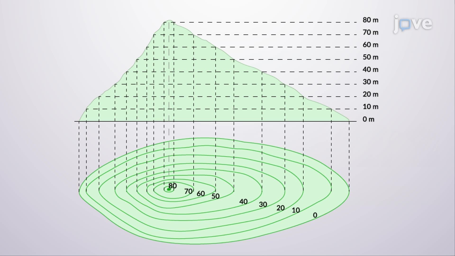
Capacity contour analysis represents a fundamental engineering technique used to predict water spread patterns in hydraulic structures. This method combines topographic surveying with hydraulic calculations to ensure safe and effective water storage design. Engineers rely on this approach for projects ranging from small retention ponds to major dam constructions across the United States.
Horizontal curves in water engineering contexts refer to the curved boundaries that water creates as it spreads across varying terrain elevations. These curves follow natural topographic patterns and help engineers visualize flood extents. Types of horizontal curves include simple curves following single elevation contours, compound curves spanning multiple elevation changes, and reverse curves where water flow changes direction around topographic features. Understanding these curve types proves essential for AP Environmental Science students studying watershed management and for college engineering students in hydraulics courses.
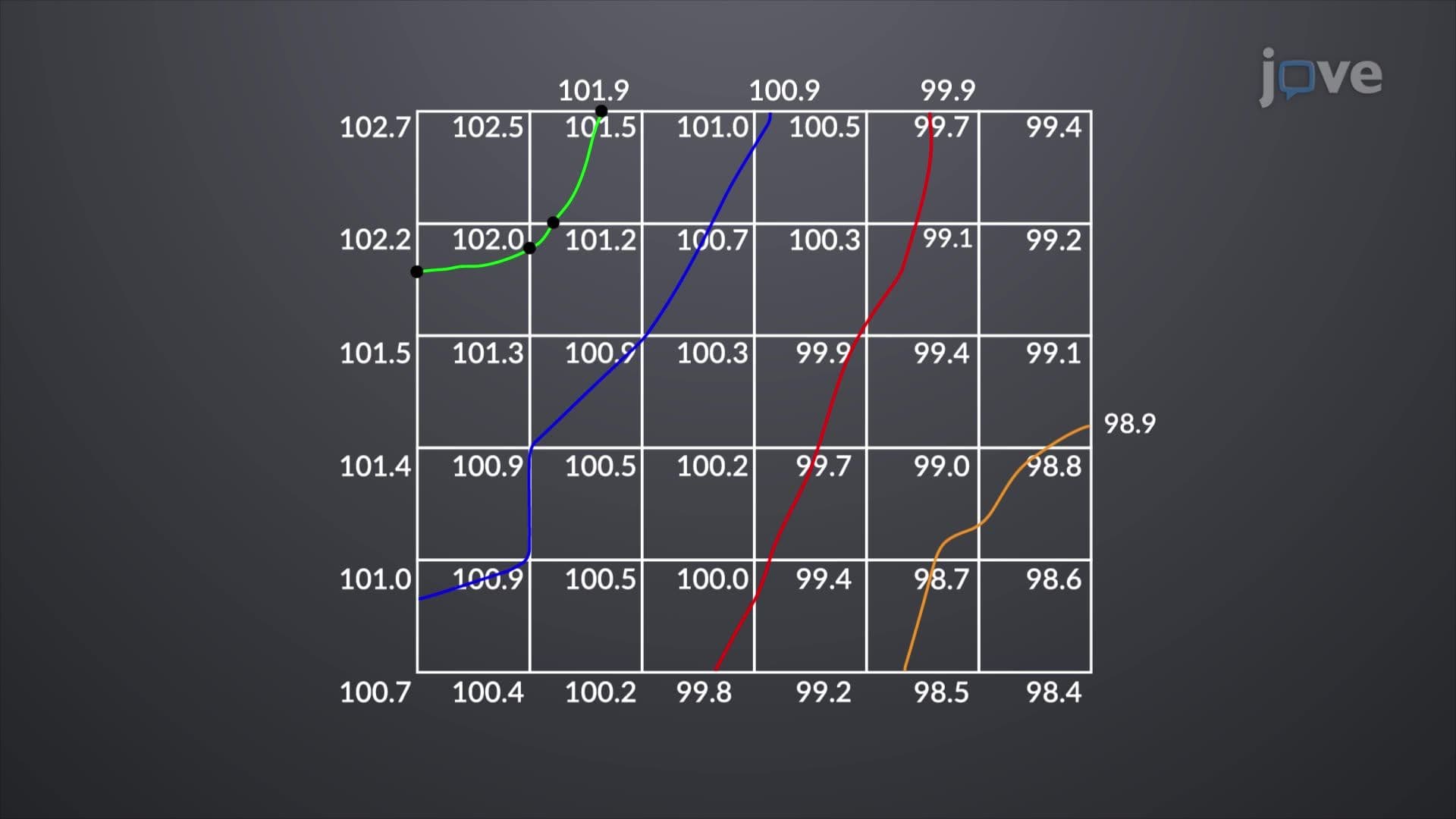
What are horizontal curves overview encompasses the systematic approach engineers use to map water boundaries at specific elevations. This process begins with establishing a reference datum point, typically the proposed structure height. Engineers then use precise surveying instruments to mark equal elevation points across the upstream area, creating horizontal reference lines that define water spread limits. This methodology appears frequently on engineering licensure exams and college hydraulics assessments.
The capacity contour method proved crucial during recent infrastructure projects like California's Oroville Dam spillway reconstruction, where accurate flood modeling prevented downstream community evacuation. Engineers must balance water storage capacity with flood safety margins, often requiring iterative design adjustments. When initial calculations show water spread extending into populated areas, engineers systematically lower structure heights until achieving safe clearance distances.
This engineering principle connects directly to climate change adaptation strategies, as increased storm intensities require more sophisticated flood control measures. Students preparing for the Fundamentals of Engineering (FE) exam encounter similar problems involving flood plain mapping and hydraulic structure design. The methodology also supports environmental impact assessments required under the National Environmental Policy Act for federal water projects.
Related Micro-courses