Loading video…


 9 Concepts
 5.2K views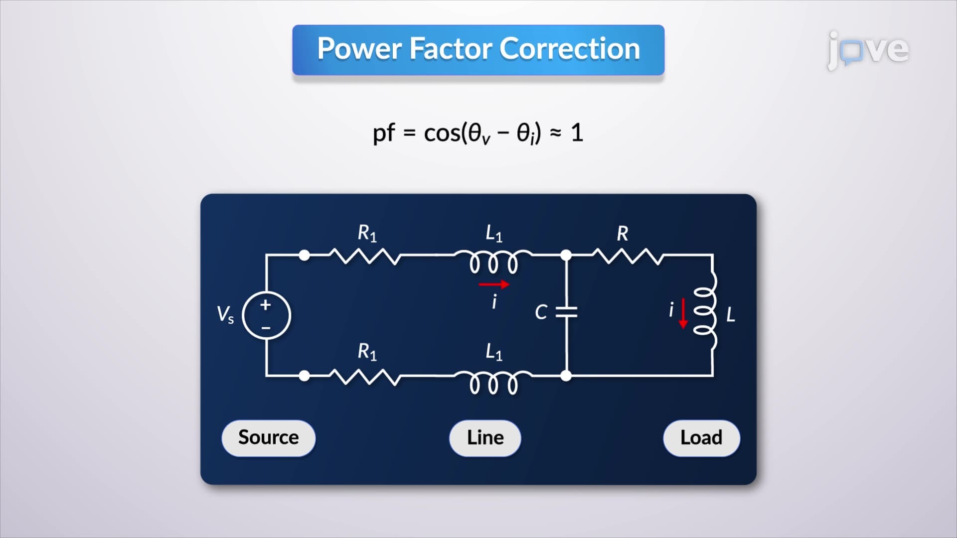

Video Summary: What Is Power Factor Correction
Ever wonder why your electricity bill spikes when factories run inefficient equipment? The power superposition principle helps explain how electrical systems can waste energy through poor power factor management. When a manufacturing plant in Detroit operates motors with low power factor, it draws excessive reactive power from the grid, creating costly inefficiencies. What is Power Factor Correction addresses this critical engineering challenge by demonstrating how capacitors can optimize electrical systems, reducing energy waste and improving overall performance. Watch the full video on JoVE Coach to master this concept with expert-led visuals and step-by-step explanations.
Power factor correction represents a fundamental electrical engineering technique used to improve the efficiency of AC electrical systems. In industrial and commercial applications across the United States, from steel mills in Pittsburgh to semiconductor fabrication plants in Silicon Valley, power factor correction directly impacts operational costs and system performance. The concept builds upon the power superposition principle, which states that the total power in an AC circuit consists of both active (real) power that performs useful work and reactive power that oscillates between source and load.
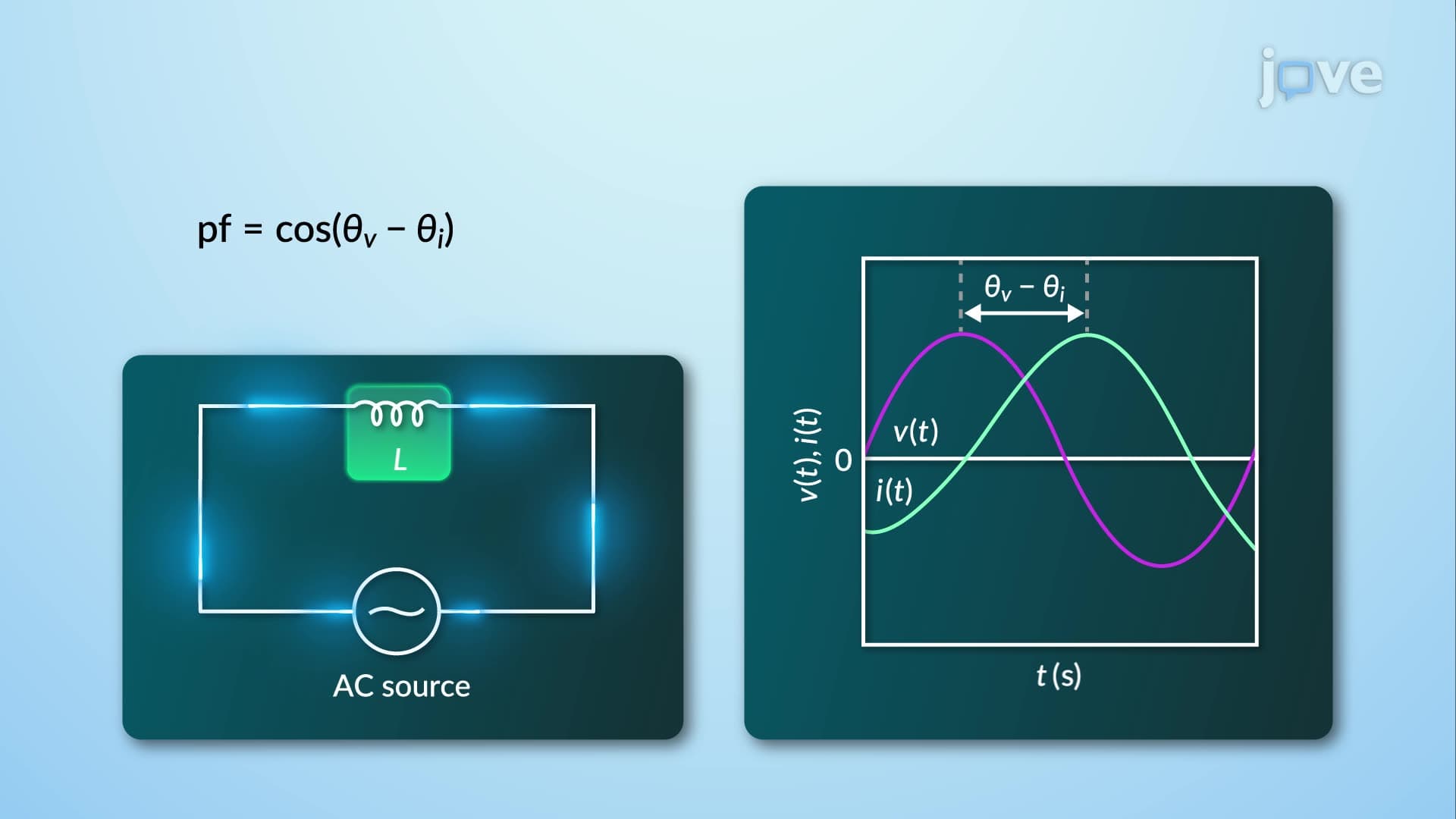
When electrical systems operate with poor power factor, typically below 0.8, they draw excessive current from utility companies without performing proportional useful work. This inefficiency manifests in several ways: increased transmission losses, higher electricity bills due to utility penalties, and potential equipment overheating. The power superposition principle definition explains how reactive components, particularly inductive loads like motors and transformers, create phase differences between voltage and current waveforms. Students preparing for AP Physics C or college-level electrical engineering courses should understand that power factor equals the cosine of this phase angle, with unity (1.0) representing perfect efficiency.
The power triangle provides a visual representation crucial for understanding what is the power superposition principle in detail. This geometric approach shows how apparent power (S) forms the hypotenuse, while active power (P) and reactive power (Q) form the adjacent and opposite sides respectively. When engineers add shunt capacitors to correct power factor, they effectively reduce the reactive power component without affecting active power. The calculation involves determining the required capacitive reactance using the formula: Q(capacitor) = P × (tan θ₁ - tan θ₂), where θ₁ represents the original power factor angle and θ₂ represents the desired corrected angle.
Major US manufacturing companies like General Electric and Ford Motor Company invest heavily in power factor correction systems to reduce operational costs. A typical automotive assembly plant might save hundreds of thousands of dollars annually through strategic capacitor bank installations. These systems automatically adjust capacitance based on load conditions, maintaining optimal power factor throughout varying production cycles. For students studying for the Fundamentals of Engineering (FE) exam, understanding these practical applications demonstrates how theoretical concepts translate into measurable economic benefits and environmental improvements through reduced energy consumption.
Related Micro-courses