Loading video…


 8 Concepts
 13K views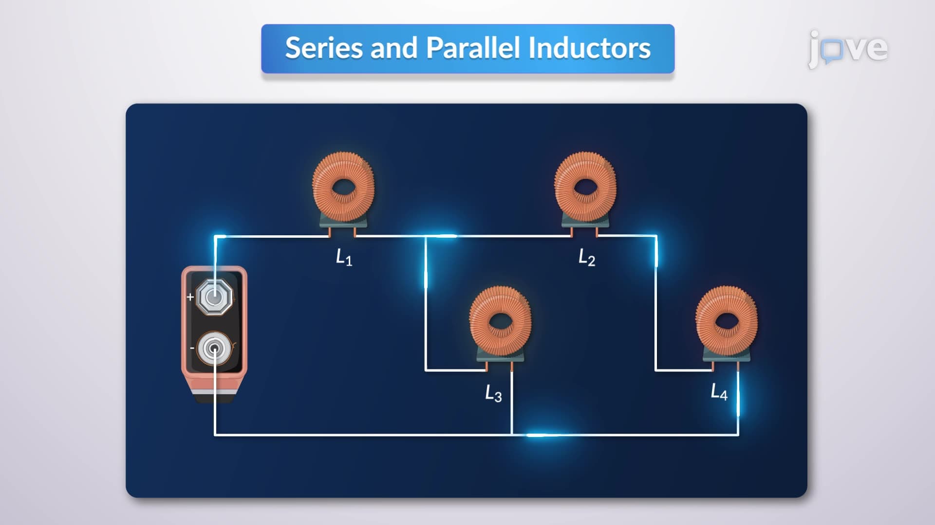

Video Summary: What Is Series and Parallel Inductors
Ever wondered how your car's ignition system generates thousands of volts from just 12V? The secret lies in understanding series and parallel inductors, which are fundamental to many design example automobile ignition system applications. In automotive electrical systems like Ford's modern ignition coils, engineers strategically combine inductors to achieve optimal performance. What is series and parallel inductors becomes crucial when designing circuits that need specific inductance values. These configurations follow mathematical rules similar to resistors but with important differences that impact real-world applications. Watch the full video on JoVE Coach to master this concept with expert-led visuals and step-by-step explanations.
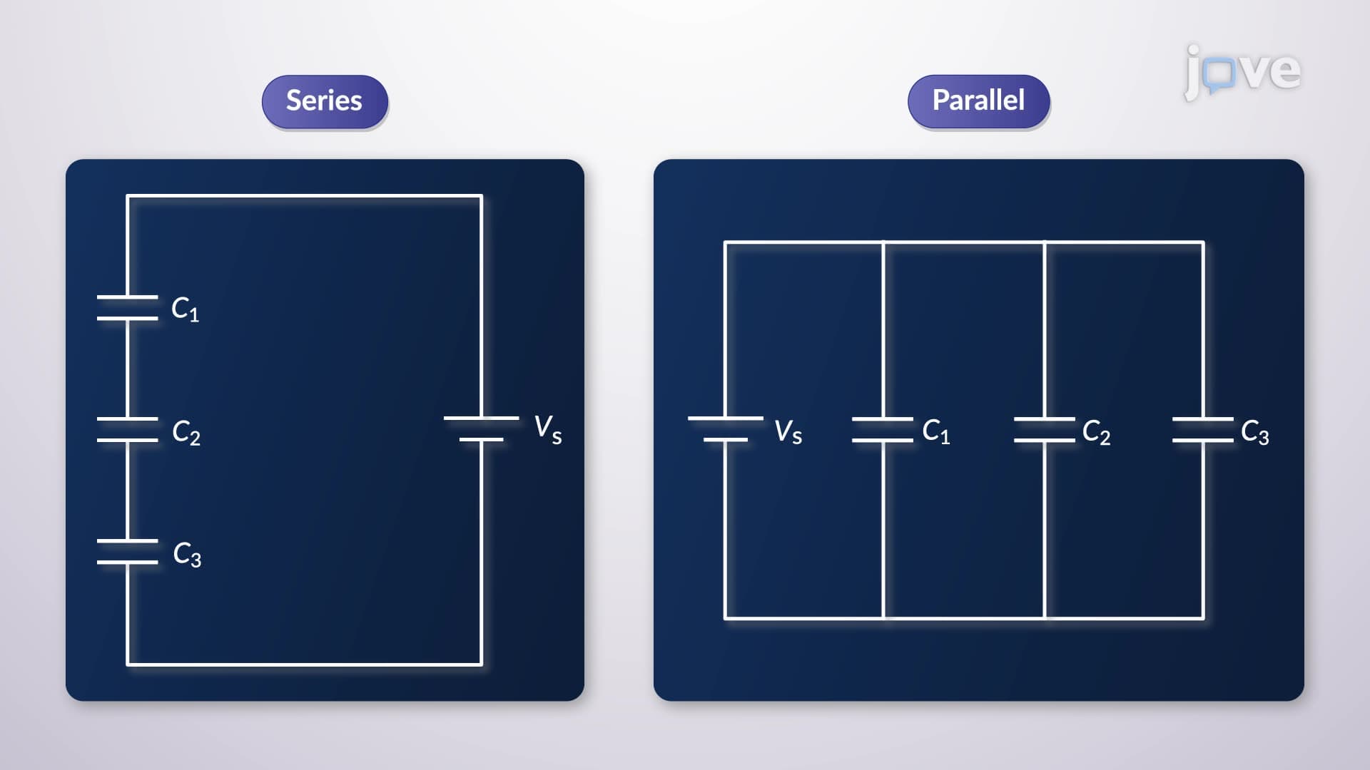
What is series and parallel inductors represents a cornerstone concept in electrical engineering that extends far beyond textbook problems. When inductors are connected in series, they share the same current, creating a cumulative effect where the total inductance equals the sum of individual inductances: L(total) = L1 + L2 + L3 + ... This additive property makes series configurations ideal for applications requiring higher inductance values than any single component can provide.
For series-connected inductors, Kirchhoff's voltage law reveals that the voltage drops across each inductor sum to the total applied voltage. Since each inductor experiences the same current but different voltage drops proportional to their inductance values, the equivalent inductance naturally becomes the arithmetic sum. This principle underlies many design example automobile ignition system applications where engineers need precise inductance control.
Parallel inductors follow a different rule entirely. When inductors share the same voltage but carry different currents, the equivalent inductance follows the reciprocal formula: 1/L(total) = 1/L1 + 1/L2 + 1/L3 + ... This relationship, derived from Kirchhoff's current law, means parallel combinations always produce lower total inductance than the smallest individual inductor.
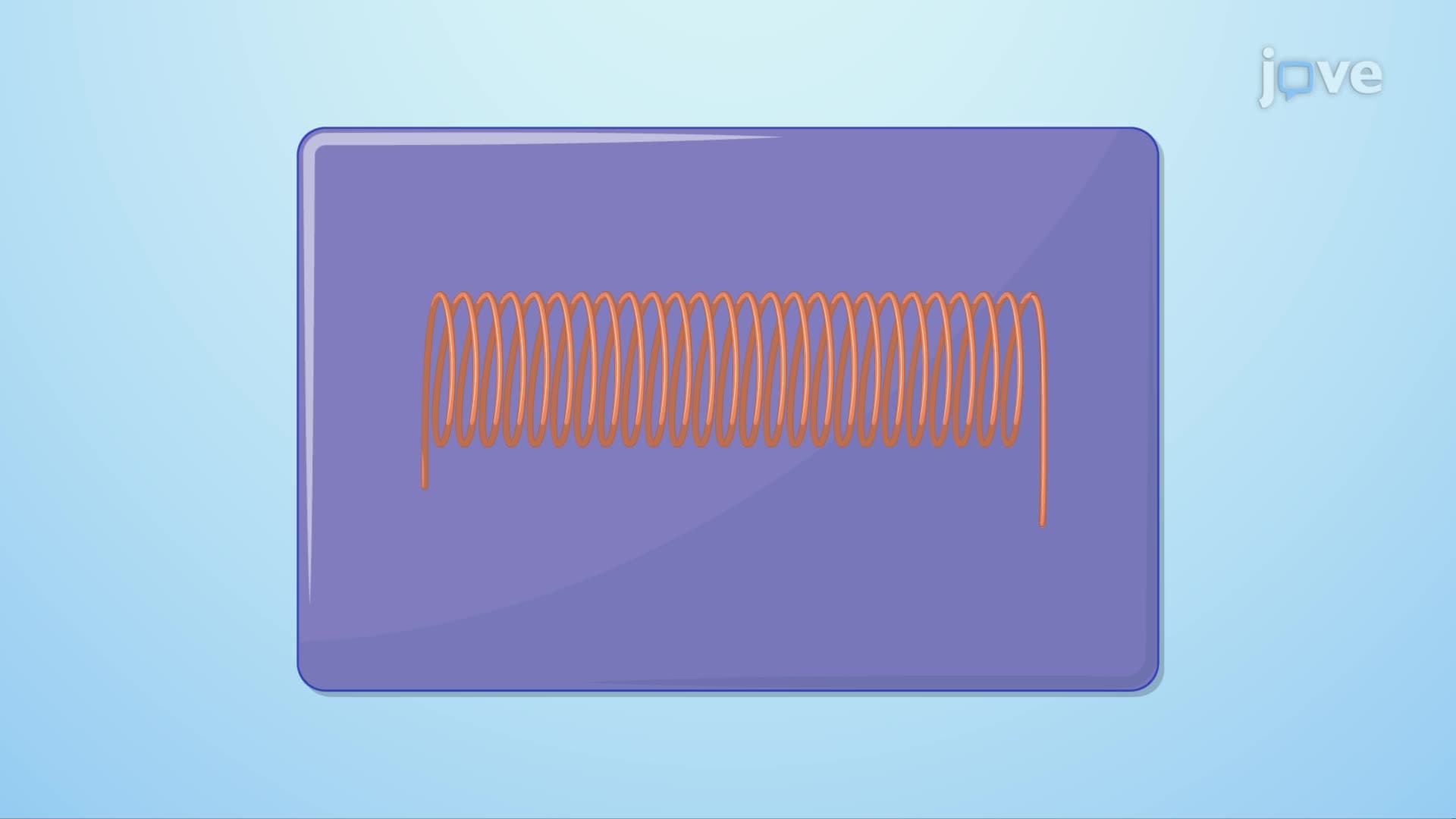
Modern American automotive manufacturers like General Motors and Tesla extensively use inductor combinations in their electrical systems. In a design example automobile ignition system tutorial context, the ignition coil itself represents a sophisticated inductor system. Primary and secondary windings work together to step up voltage, while additional filter inductors in parallel help reduce electromagnetic interference that could affect sensitive engine control modules.
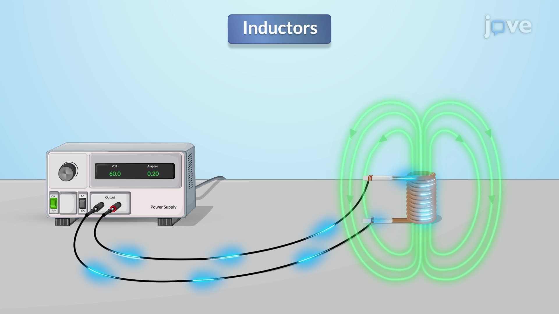
Understanding how design example automobile ignition system works requires recognizing that the ignition coil's primary winding stores energy when current flows, then releases it rapidly when the current is interrupted. This energy transfer, governed by the inductor's stored energy formula E = (1/2)LI², depends critically on achieving the correct inductance value through proper series and parallel combinations.
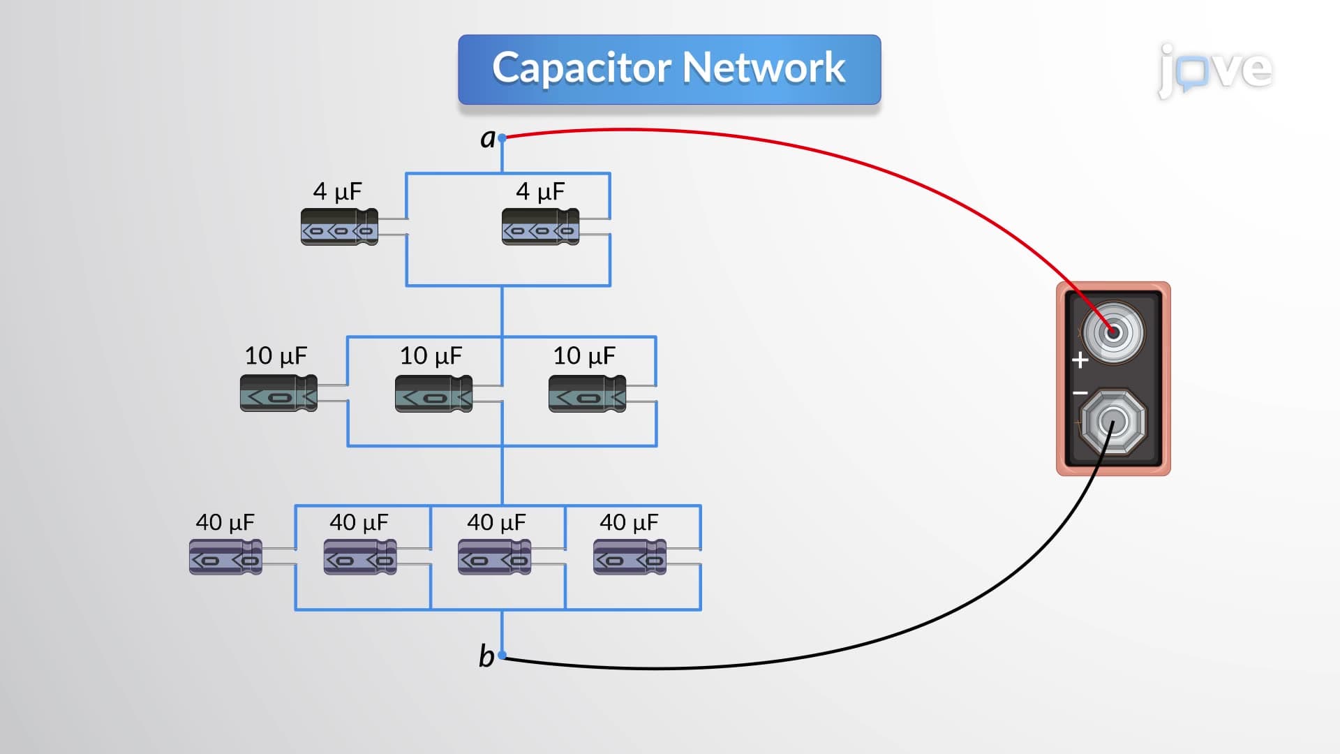
AP Physics C and college-level electrical engineering courses frequently test inductor combination concepts through circuit analysis problems. Students encounter these topics in standardized tests where they must calculate equivalent inductance for complex networks. The key strategy involves systematically identifying series and parallel sections, then working step-by-step from the most deeply nested combinations outward to find the overall equivalent inductance.
Related Micro-courses