Loading subject page…


6,613 views

Video Summary: What are Measurements of Strain
Did you know that engineers measuring the Golden Gate Bridge's flexibility during earthquakes rely on the same principles used to test materials in your high school physics lab? Measurements of strain reveal how materials deform under stress, from bridge cables stretching under wind loads to concrete foundations compressing during seismic events. These measurements use sophisticated electrical strain gauges that detect microscopic changes in material dimensions. Watch the full video on JoVE Coach to master this concept with expert-led visuals and step-by-step explanations.
Measurements of strain form the foundation of materials testing and structural engineering analysis. Strain quantifies how much a material deforms relative to its original dimensions when subjected to external forces. Unlike stress, which measures force per unit area, strain is dimensionless-representing the ratio of deformation to original length. This concept appears frequently on AP Physics exams and forms core curriculum in college-level statics and materials science courses.
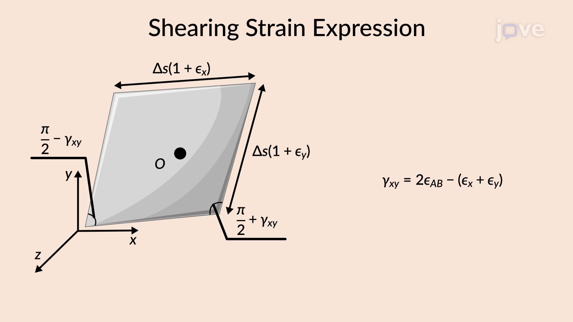
Engineers distinguish between two primary types of measurements of strain: normal strain and shearing strain. Normal strain occurs when materials stretch or compress along their length, such as a steel cable supporting a suspension bridge or concrete pillars bearing building loads. Shearing strain involves angular deformation, like the twisting motion in drive shafts or the lateral displacement in earthquake-resistant building designs.
Normal strain calculations compare original and final lengths using the formula: strain = (final length - original length) / original length. For example, if a 10-foot steel beam stretches to 10.005 feet under load, the normal strain equals 0.0005 or 0.05%.
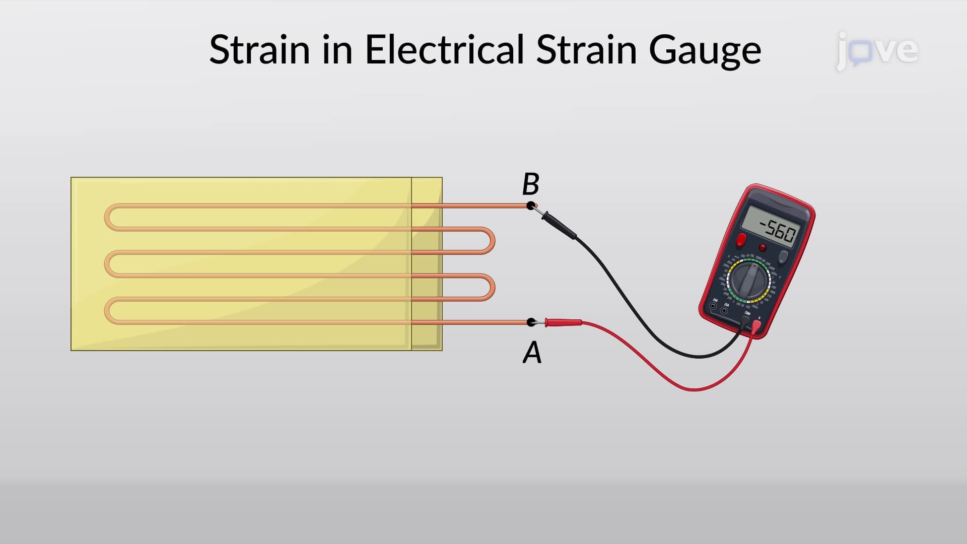
Modern measurements of strain rely heavily on electrical strain gauges-precision instruments consisting of thin metallic wires or foils bonded to flexible backing materials. When attached to test specimens, these gauges experience identical deformation as the underlying material. As the material elongates, the gauge wire lengthens and its cross-sectional area decreases, increasing electrical resistance according to fundamental physics principles.
This resistance change correlates directly with strain magnitude, allowing engineers to measure deformations as small as one millionth of an inch. NASA uses similar technology to monitor spacecraft hull integrity during launch, while automotive manufacturers employ strain gauges to test crash safety components meeting federal safety standards.
Professional strain analysis requires understanding deformation in multiple directions simultaneously. Strain rosettes-arrangements of multiple strain gauges at specific angles-provide comprehensive measurement capabilities. The most common configurations include 45° rosettes (three gauges at 0°, 45°, and 90°) and 60° rosettes (three gauges at 0°, 60°, and 120°).
These multi-gauge systems enable engineers to determine complete strain states at critical points, essential for analyzing complex loading conditions in aircraft wings, pressure vessels, and seismic-resistant structures. Students encountering this material in college engineering courses should focus on understanding how individual measurements combine to reveal overall material behavior patterns.
Related Micro-courses