Loading video…


 9 Concepts
 9.2K views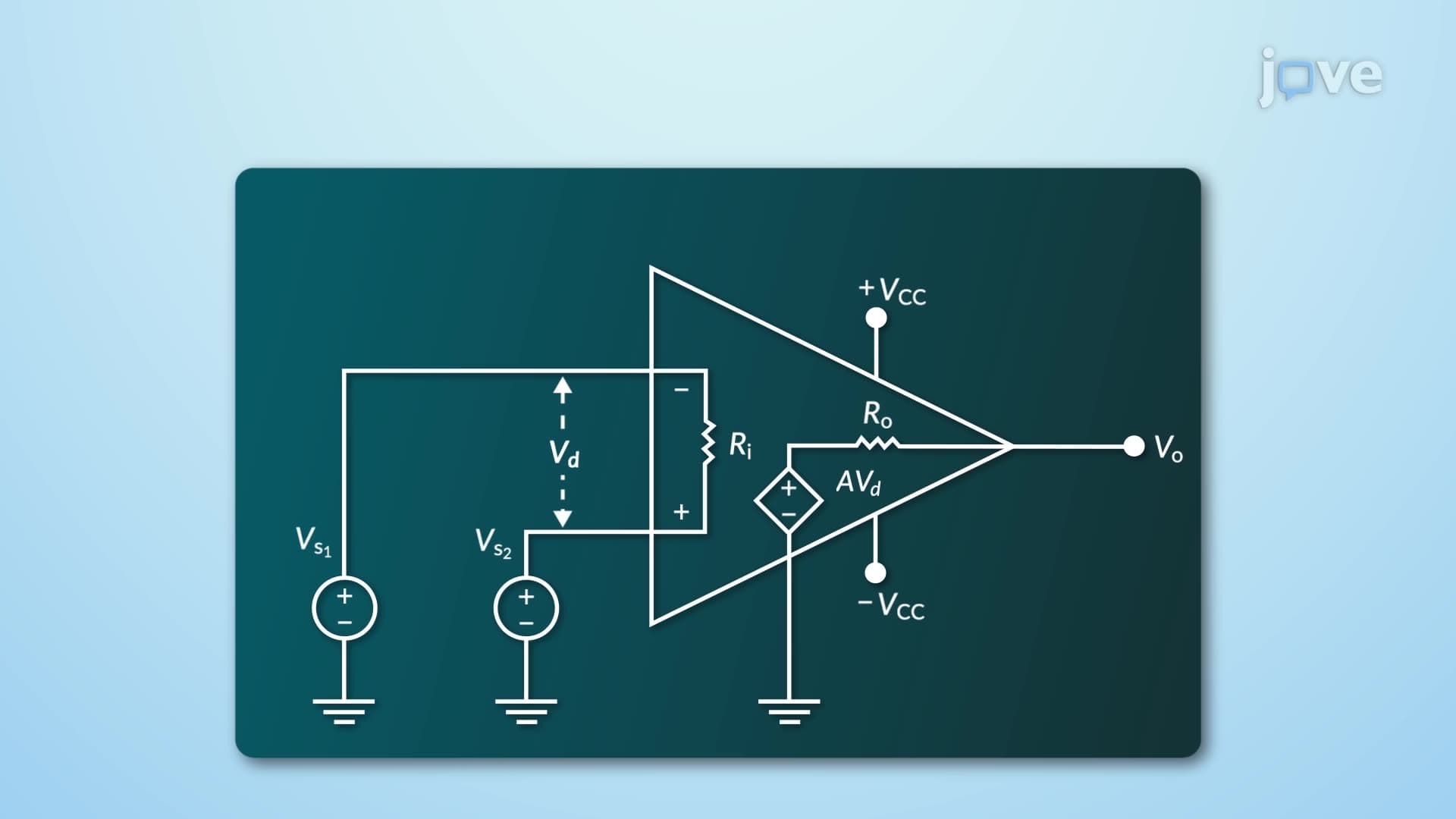

Video Summary: What are Characteristics of Opamp
Did you know that the tiny operational amplifiers powering your smartphone's audio system can theoretically amplify signals by millions of times? Inverting and non inverting opamps form the backbone of countless electronic devices, from medical equipment at Johns Hopkins Hospital to NASA's spacecraft control systems. Understanding the characteristics of opamp circuits-including their ideal properties like infinite gain and zero output resistance-is crucial for anyone studying electronics. Watch the full video on JoVE Coach to master this concept with expert-led visuals and step-by-step explanations.
What are characteristics of opamp circuits that make them so versatile in modern electronics? Operational amplifiers represent one of the most important building blocks in analog circuit design, with applications ranging from simple audio amplifiers in consumer electronics to precision instrumentation in medical devices. The fundamental characteristics stem from their internal structure: a differential input stage that compares voltages at inverting and non-inverting terminals, followed by high-gain amplification stages, and finally an output buffer stage.
The inverting and non inverting opamps concept begins with understanding ideal characteristics. An ideal operational amplifier exhibits infinite open-loop gain, meaning even the smallest voltage difference between input terminals results in maximum output swing. This theoretical device also possesses infinite input resistance, drawing zero current from source circuits-a crucial feature for measurement applications like those used in Fluke multimeters or Keysight oscilloscopes.
Real operational amplifiers, such as the popular Texas Instruments LM741 or Analog Devices OP07, approximate these ideal characteristics remarkably well. Modern devices achieve open-loop gains exceeding 100,000 and input resistances in the megohm range. However, practical limitations include finite bandwidth (typically measured in MHz), non-zero input bias currents (measured in picoamps), and output resistance that can affect high-frequency performance.
The magic of inverting and non inverting opamps lies in their linear operation region. When negative feedback connects the output to the inverting input through resistive networks, the amplifier operates in its linear range, preventing saturation. This principle underlies countless applications: audio amplifiers in Marshall guitar amps, precision voltage followers in data acquisition systems, and active filters in telecommunications equipment.
Students preparing for AP Physics C or introductory electronics courses should understand that saturation occurs when output attempts to exceed supply voltage limits. For instance, an opamp powered by ±15V supplies cannot produce outputs beyond this range, regardless of input conditions.
Understanding how inverting and non inverting opamps works proves essential for students pursuing electrical engineering at institutions like MIT, Stanford, or Georgia Tech. These concepts appear frequently on MCAT physics sections, particularly in passages about medical instrumentation. Real-world applications include ECG amplifiers in hospital equipment, precision current sources in semiconductor testing, and active filters in automotive engine control units manufactured by companies like Delphi or Bosch.
Related Micro-courses