Loading video…


 9 Concepts
 9.2K views

Video Summary: What Is Instrumentation Amplifier
Ever wondered how a design example vintage mixing console amplifies tiny electrical signals from microphones without picking up unwanted noise? The secret lies in instrumentation amplifiers-specialized circuits that can boost signals by thousands of times while rejecting interference. From recording studios at Abbey Road to biomedical devices measuring heartbeats, these amplifiers form the backbone of precision electronics. Understanding what is instrumentation amplifier reveals how engineers solve real-world signal processing challenges. Watch the full video on JoVE Coach to master this concept with expert-led visuals and step-by-step explanations.
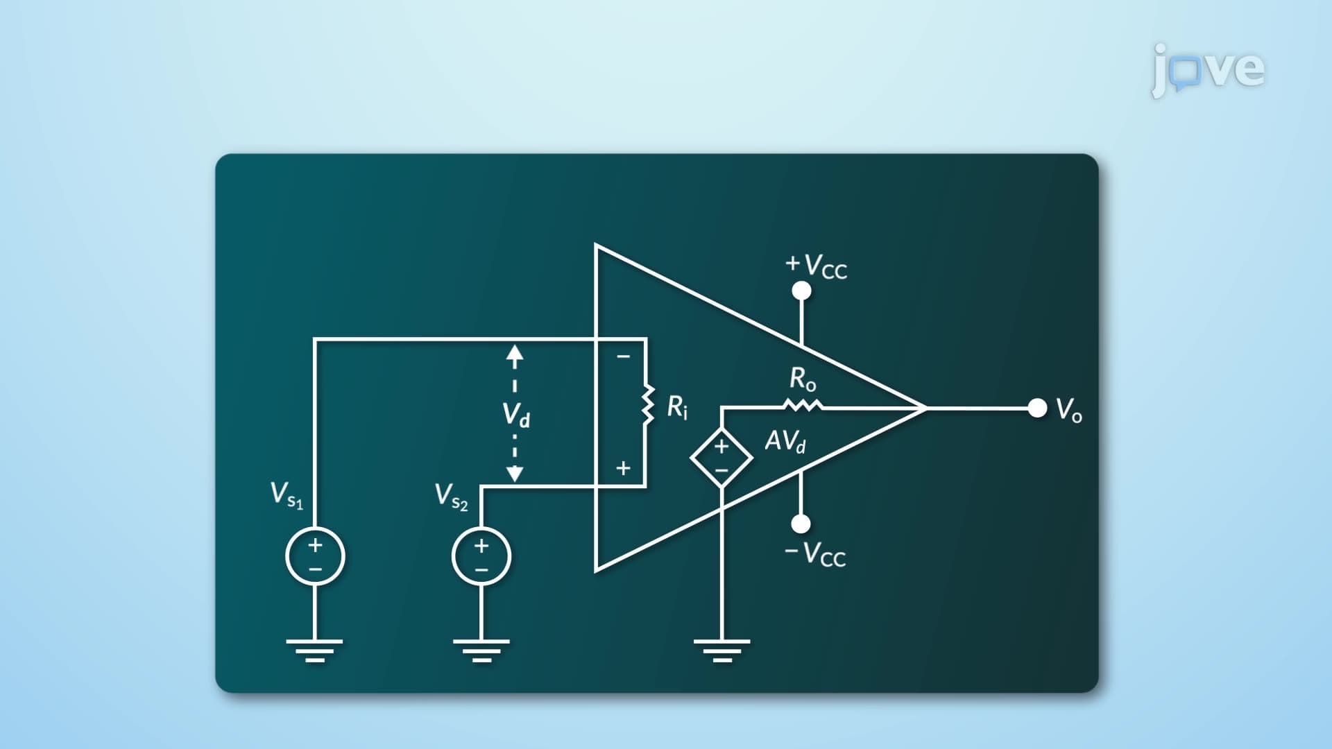
An instrumentation amplifier represents one of the most elegant solutions in analog circuit design for amplifying small differential signals while rejecting noise. Unlike a simple operational amplifier, this three-op-amp configuration provides exceptional performance characteristics that make it indispensable in precision applications. The circuit consists of two input buffer amplifiers followed by a difference amplifier stage, creating a system with extremely high input impedance (typically over 10^9 ohms) and exceptional common-mode rejection ratios exceeding 100 dB.
In professional audio equipment, particularly in design example vintage mixing console setups, instrumentation amplifiers serve as the first stage for microphone preamplification. Studios like Capitol Records and Electric Lady Studios rely on these circuits to capture subtle musical nuances without introducing noise. The high input impedance prevents loading of sensitive microphones, while the differential input design rejects electromagnetic interference from lighting systems and other studio equipment. Modern mixing consoles in Nashville's Music Row continue this tradition, using instrumentation amplifiers to maintain signal integrity from microphone to final mix.
The most critical applications appear in biomedical instrumentation, where instrumentation amplifiers enable life-saving measurements. ECG machines at hospitals like Johns Hopkins and Mayo Clinic use these circuits to detect microvolt-level heart signals while rejecting 60 Hz power line interference. The amplifier's ability to reject common-mode signals-noise that appears equally on both inputs-proves essential when electrode leads pick up electrical interference from hospital equipment. Similarly, EEG systems recording brain activity rely on instrumentation amplifiers to detect signals 1000 times smaller than typical electronic noise levels.
For students preparing for AP Physics C or college-level electronics courses, understanding instrumentation amplifier gain calculations proves essential. The gain equation G = 1 + (2R/Rg) demonstrates how a single external resistor (Rg) controls amplification. When Rg = 1000 ohms and R = 50,000 ohms, the gain equals 101, providing substantial signal boost. This elegant control method appears frequently on MCAT physics sections and engineering coursework at universities like MIT and Stanford. Students should practice calculating gains for different resistor values and understand how this relates to real measurement requirements in laboratory settings.
Related Micro-courses