Loading subject page…

- Mechanical Engineering
- Transformations of Stress and Strain
- Mohr's Circle for Plane Strain
Micro-course: Transformations of Stress and Strain
6,613 views
Learn key concepts and earn your certificate.



Mohr's Circle for Plane Strain

00:00
01:18
Video Summary: Mohrs Circle for Plane Strain Explained
Ever wondered how aerospace engineers at Boeing analyze wing deformation during flight testing? Mohr's circle for plane strain provides a brilliant graphical method to visualize how materials deform under complex loading conditions. This powerful engineering tool plots normal strain on the horizontal axis and half the shearing strain on the vertical axis, creating a circle that reveals maximum and minimum principal strains at critical points. Watch the full video on JoVE Coach to master this concept with expert-led visuals and step-by-step explanations.
- Understand how Mohr's Circle For Plane Strain graphically represents strain transformations in two-dimensional stress analysis
- Identify the key components of Mohr's circle including center coordinates, radius calculations, and principal strain locations
- Analyze the relationship between coordinate axis rotation and corresponding point movement on the strain circle
- Apply the graphical method to determine maximum and minimum principal strains from given strain components
- Recognize how principal strain axes align with stress axes in elastic, homogeneous, and isotropic materials
- Evaluate maximum in-plane shearing strain using the circle's diameter measurements
- Explore the connection between Hooke's law and the geometric relationships within Mohr's circle construction
- Compare strain transformations through angular rotations using the 2θ rule on the circle diagram
Understanding Mohr's Circle For Plane Strain Fundamentals
Mohr's circle for plane strain serves as an indispensable graphical tool in structural and mechanical engineering, transforming complex mathematical strain calculations into intuitive visual representations. Unlike stress analysis, strain analysis focuses on material deformation characteristics, making it crucial for understanding how structures behave under various loading conditions.
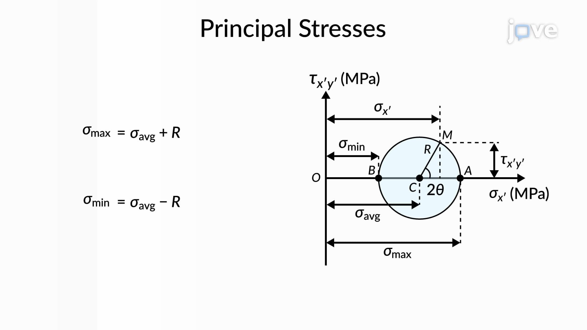
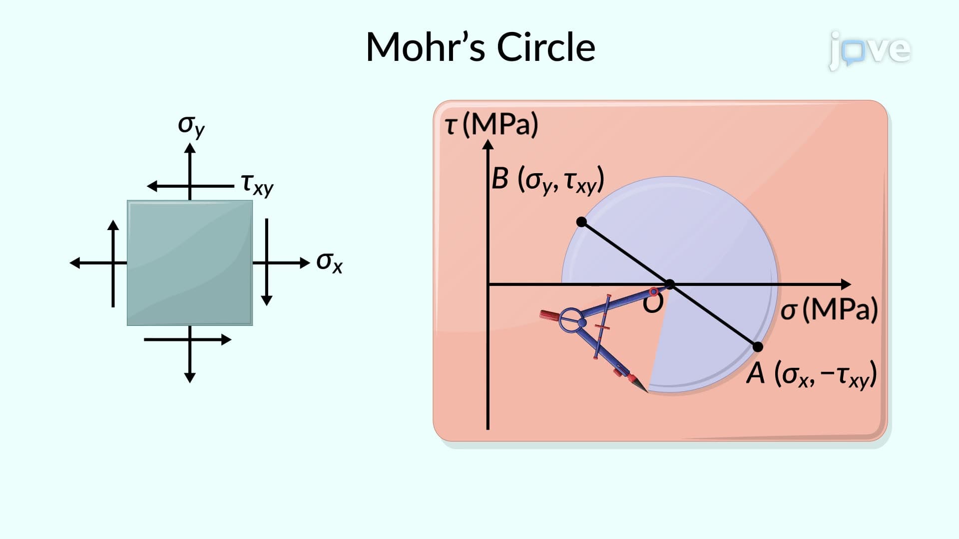
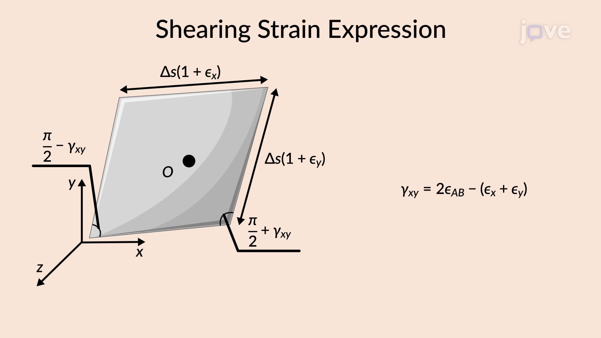
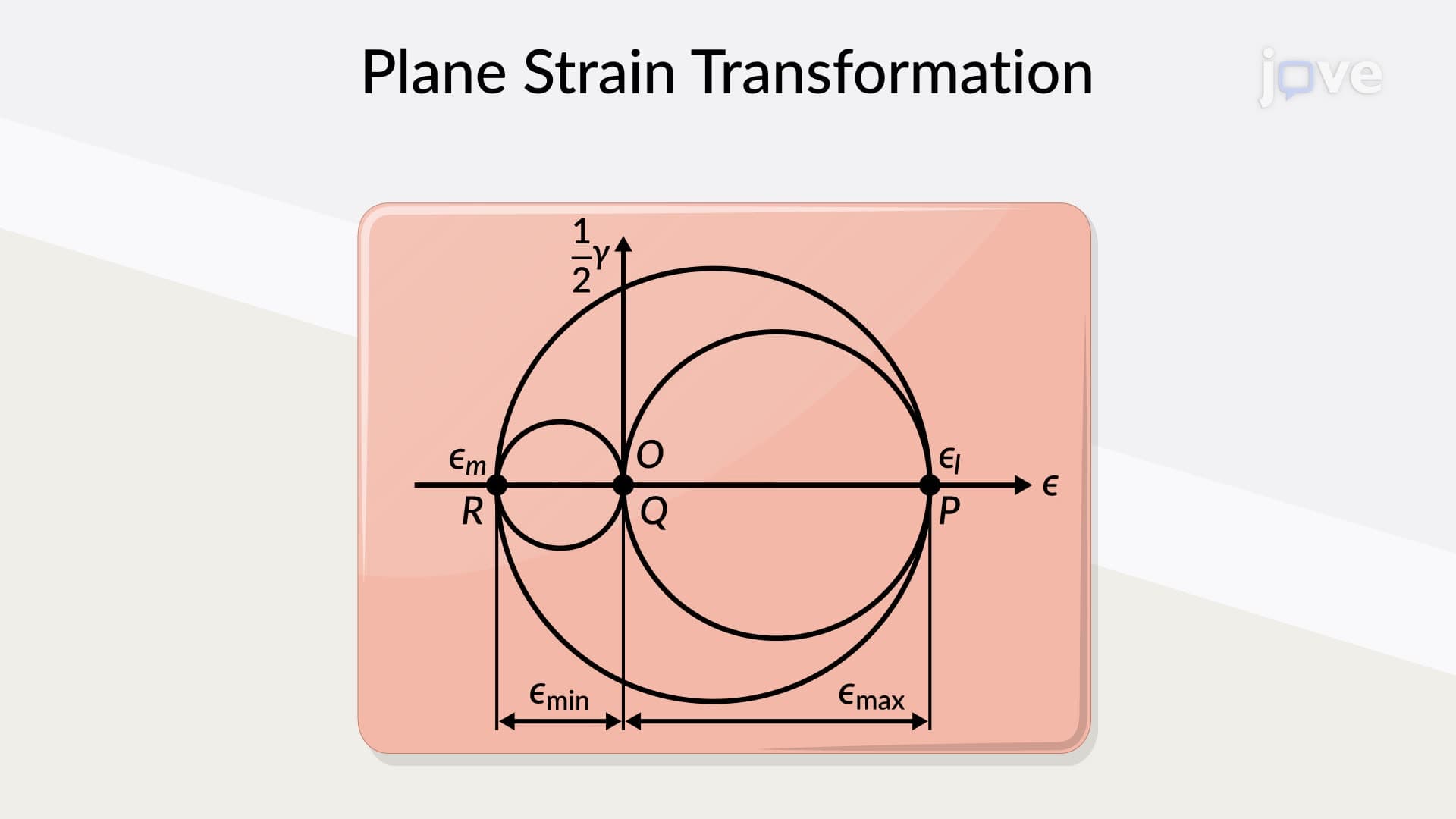
The construction begins by establishing a coordinate system where the horizontal axis (abscissa) represents normal strain values, while the vertical axis (ordinate) represents half the shearing strain. This unique plotting convention creates a circular representation that elegantly captures all possible strain states at a given point within a material.
Center Point and Radius Calculations
The circle's center O is strategically positioned at coordinates determined by the average normal strain, calculated as (εx + εy)/2. This center point represents the invariant strain component that remains constant regardless of coordinate system orientation. The radius extends from this center to encompass the strain variation range, calculated using the formula: R = √[((εx - εy)/2)² + (γxy/2)²].
These geometric parameters directly relate to physical material behavior. For instance, when analyzing bridge deck deformation under vehicle loading, engineers use these calculations to predict maximum strain concentrations that could lead to structural failure.
Principal Strains and Maximum Shearing Strain
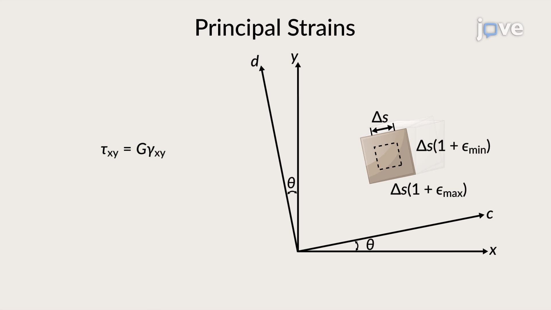
The circle's intersections with the horizontal axis reveal the maximum and minimum principal strains-critical values for failure analysis in engineering applications. These principal strains occur at orientations where shearing strain equals zero, representing pure normal deformation states.
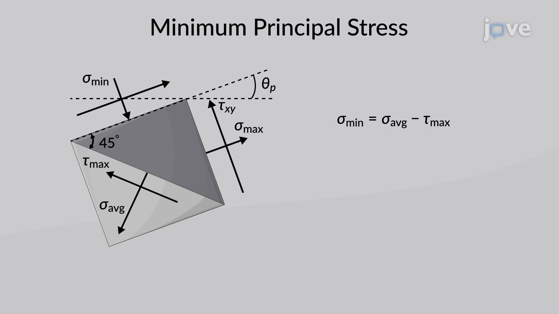
Maximum in-plane shearing strain equals the circle's diameter, occurring at 45-degree orientations from the principal strain directions. This relationship proves essential in materials testing, particularly when designing components for aerospace applications where weight optimization requires operating near material limits.
Practical Applications in Engineering Analysis
During elastic deformation in homogeneous, isotropic materials, principal strain axes coincide with principal stress axes, following Hooke's law relationships. This alignment simplifies analysis significantly, allowing engineers to predict material response using either stress or strain approaches interchangeably.
Students preparing for AP Physics or college-level mechanics courses will encounter these concepts in structural analysis problems, materials science applications, and failure prediction scenarios. The graphical nature makes complex three-dimensional strain states comprehensible through two-dimensional circular representations.
Frequently Asked Questions
Mohr's Circle For Plane Strain is a graphical method that represents strain transformations in two dimensions, focusing on material deformation rather than applied forces. Unlike stress analysis that examines force distributions, strain analysis reveals how materials actually deform, making it essential for predicting structural behavior and material failure. The circle plots normal strain horizontally and half the shearing strain vertically, creating an intuitive visualization of complex deformation states.
AP Physics C: Mechanics and college engineering exams typically present problems requiring graphical strain analysis or numerical calculations using circle properties. Students must identify principal strains, calculate maximum shearing strains, and determine strain components at specific angles. Practice problems often involve beam bending, pressure vessel analysis, or structural member evaluation scenarios.
The MCAT focuses on conceptual understanding rather than complex calculations, emphasizing relationships between stress, strain, and material properties. Key concepts include Hooke's law applications, elastic modulus relationships, and basic strain definitions. Students should understand how strain relates to structural deformation in biological systems like bone loading or cardiovascular mechanics.
Civil engineers analyzing the Golden Gate Bridge or similar structures use strain circles to evaluate deck plate deformation under traffic loading. They determine critical strain concentrations at connection points, assess fatigue life predictions, and optimize structural member sizing. The graphical method helps visualize complex loading scenarios where multiple force directions create intricate strain patterns.
Basic trigonometry and algebra skills suffice for understanding fundamental Mohr's circle concepts and applications. While advanced engineering applications may require calculus for derivations, the core graphical method relies on geometric relationships and coordinate transformations. Students with strong geometry backgrounds can master the essential concepts without extensive calculus knowledge.
Practice drawing circles from given strain data, starting with simple cases and progressing to complex multi-axis loading scenarios. Focus on understanding the geometric relationships rather than memorizing formulas, since the visual approach reinforces mathematical concepts. Work through practice problems involving real structures like building frames or machine components to develop practical intuition.
Progress to three-dimensional strain analysis using Mohr's circles for spatial stress states, then explore advanced topics like strain rosette analysis, photoelasticity, and finite element methods. Students interested in materials science should investigate crystal mechanics and composite material behavior, while those pursuing structural engineering can advance to dynamic loading and fatigue analysis applications.
Related Micro-courses


