Loading video…


 14 Concepts
 24.5K views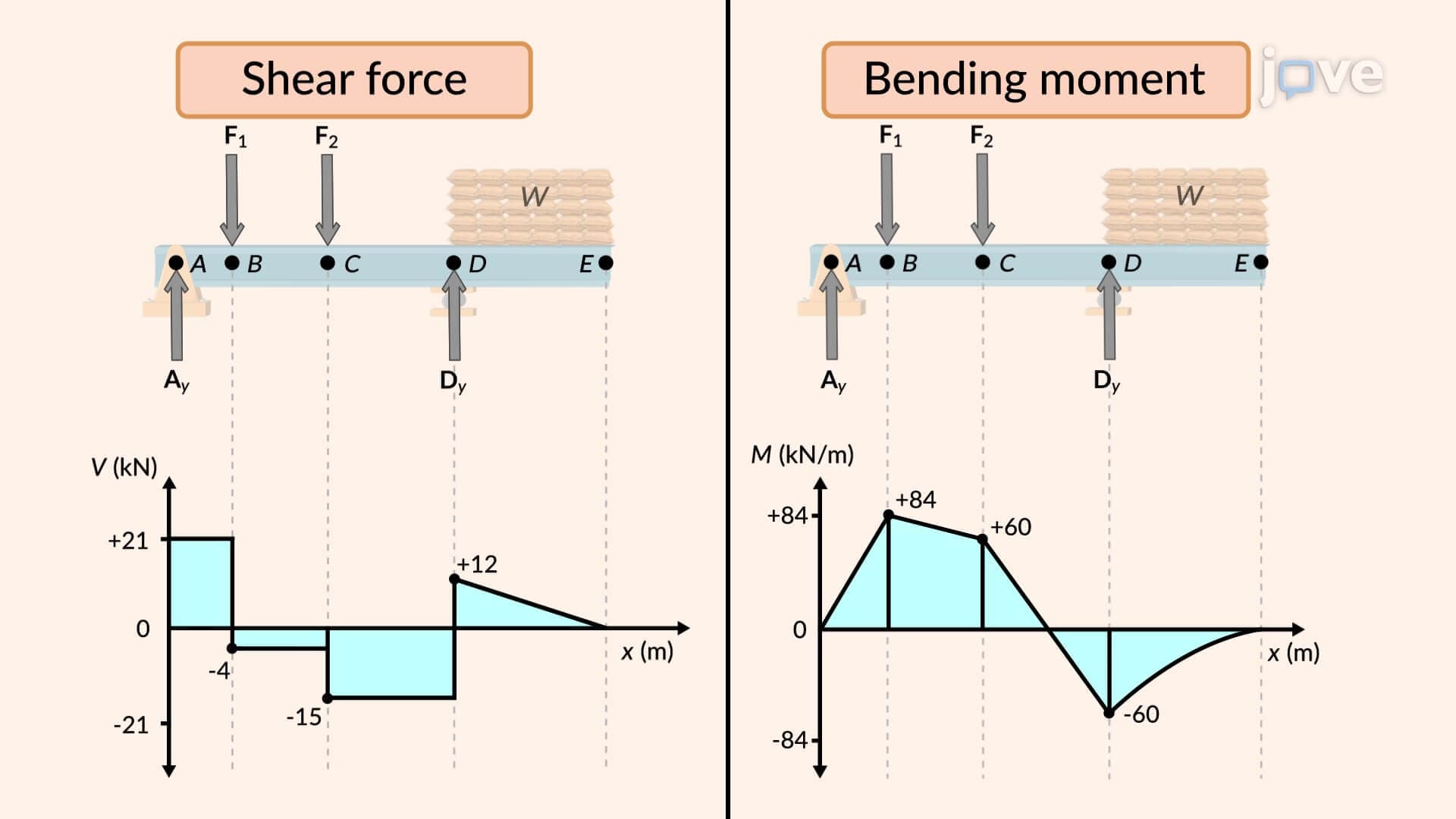

Video Summary: Shear and Bending Moment Diagram Guide
Ever wonder why the Golden Gate Bridge doesn't collapse under the weight of thousands of cars? The secret lies in understanding how forces create internal stresses within structural beams. A shear and bending moment diagram reveals exactly how loads distribute through any beam, from massive suspension bridge cables to simple wooden planks in your home's floor joists. This fundamental engineering concept transforms complex force interactions into clear, visual representations that predict structural behavior. Watch the full video on JoVE Coach to master this concept with expert-led visuals and step-by-step explanations.
The shear and bending moment diagram serves as the structural engineer's roadmap, revealing internal forces that determine whether a beam will safely carry its intended loads. These diagrams transform abstract force concepts into visual tools that predict structural behavior with mathematical precision.
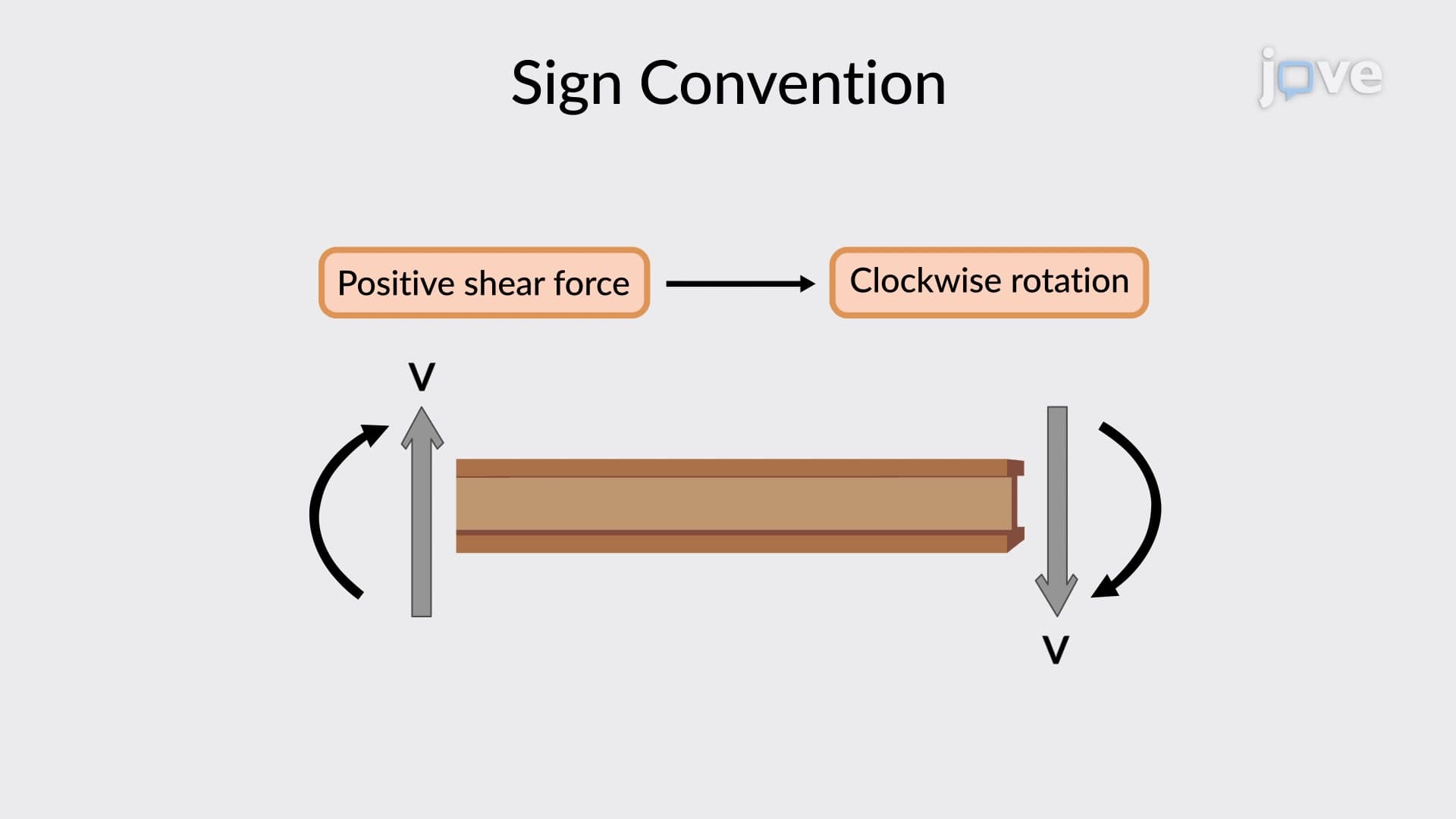
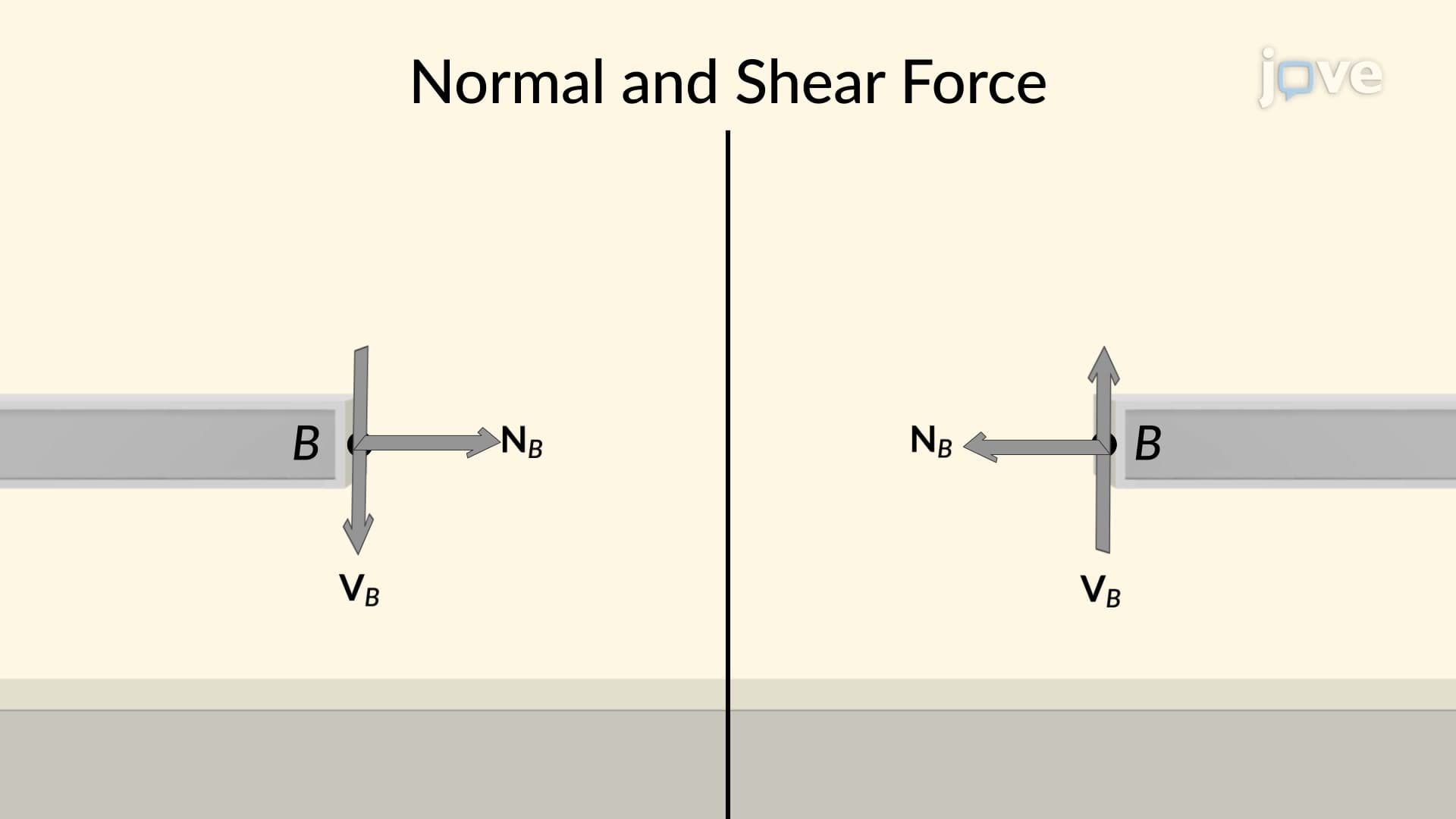
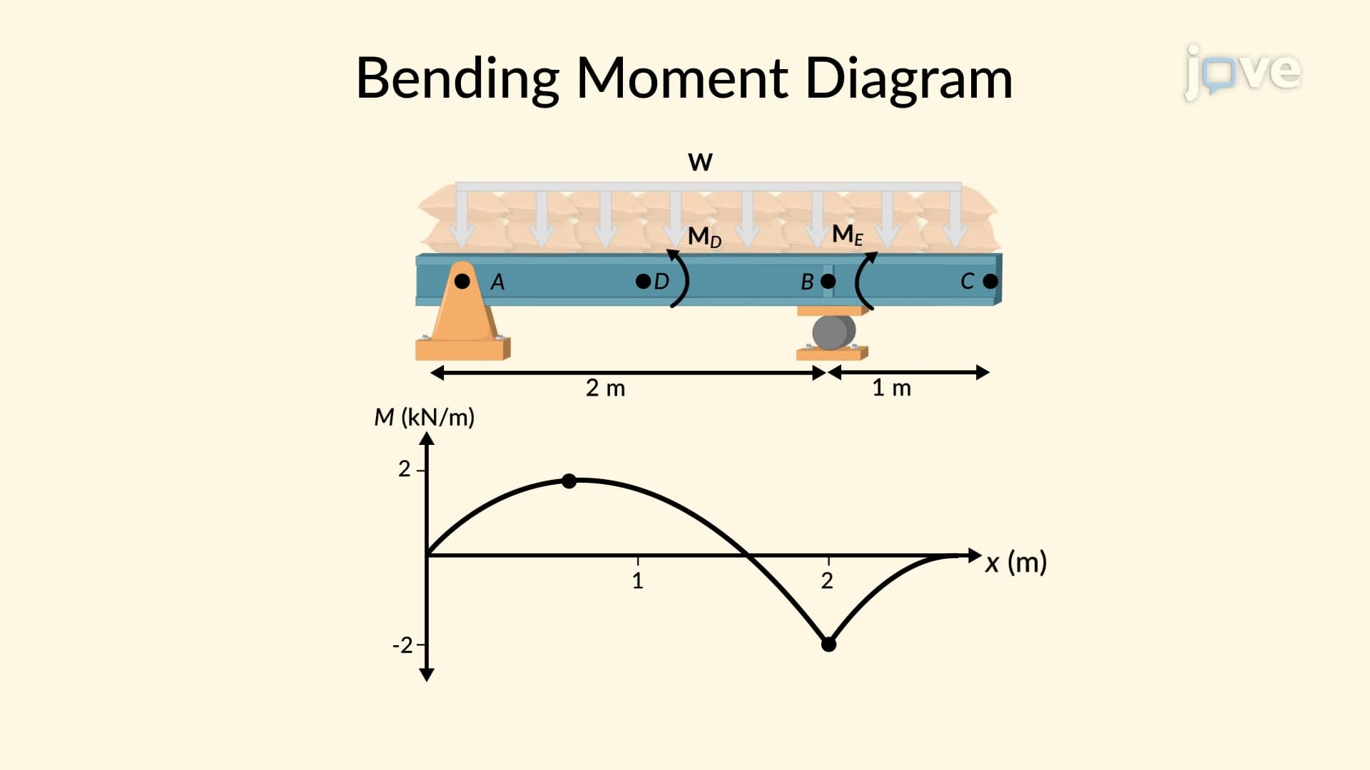
When loads act on a beam, two critical internal forces develop: shear forces and bending moments. Shear forces represent the tendency for one part of the beam to slide past an adjacent part, similar to how scissors cut paper. Bending moments describe the beam's tendency to bend or curve under load, like a diving board flexing under a swimmer's weight.
In practical applications, these forces determine structural design requirements. The Tacoma Narrows Bridge collapse in 1940 demonstrated the catastrophic consequences of inadequately accounting for these internal forces. Modern structures, from the Willis Tower in Chicago to everyday residential floor joists, rely on accurate shear and bending moment analysis.
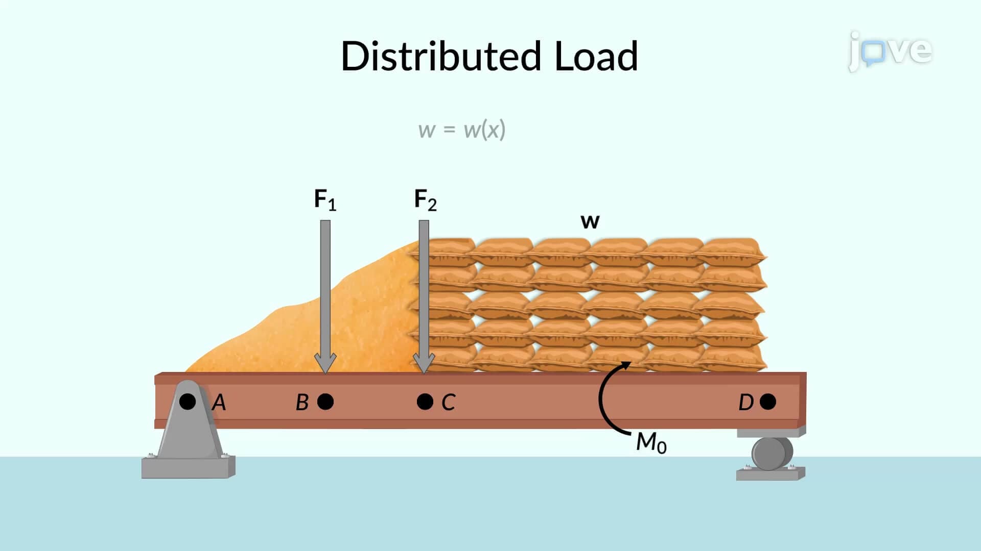
The construction process begins with establishing equilibrium. Engineers draw free-body diagrams and apply equilibrium equations (sum of forces equals zero, sum of moments equals zero) to determine support reactions. For a typical beam supporting concentrated and distributed loads, this might involve calculating upward reactions at supports that balance downward applied loads.
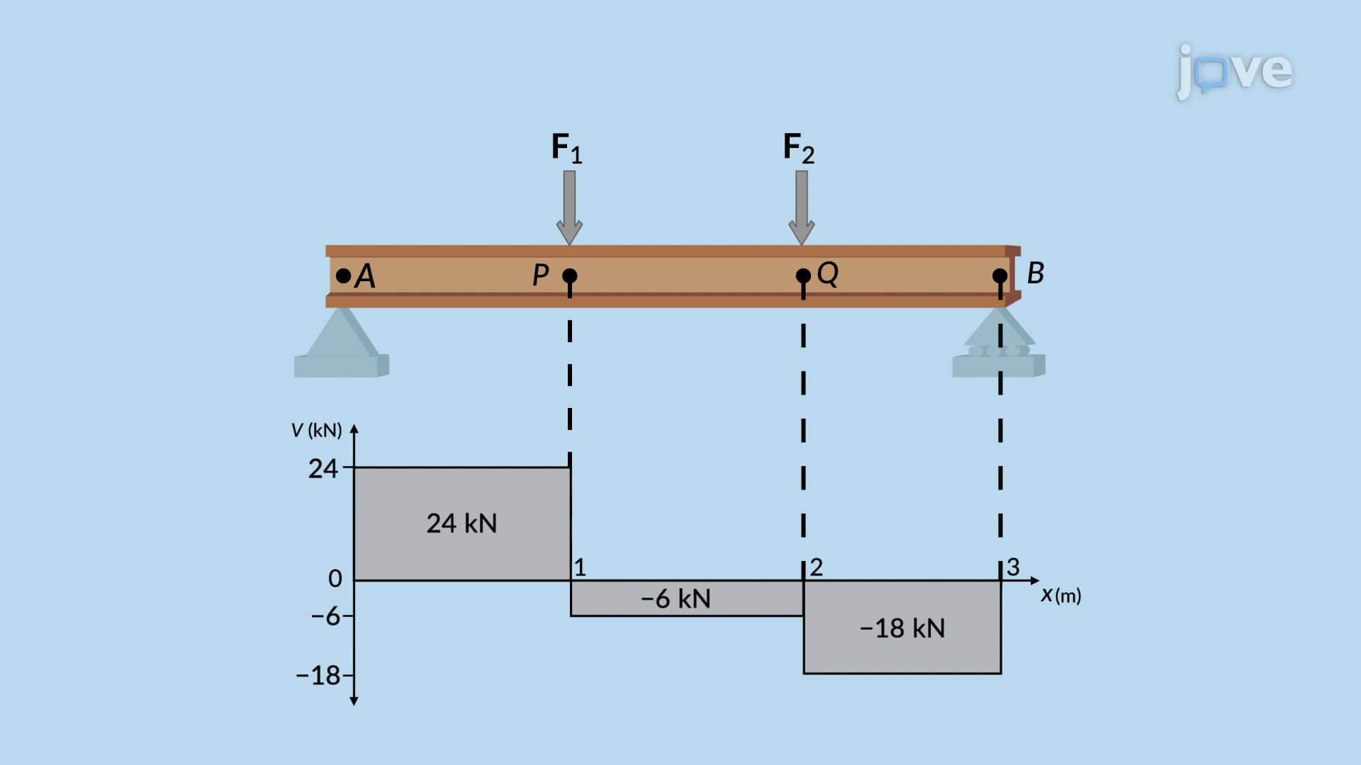
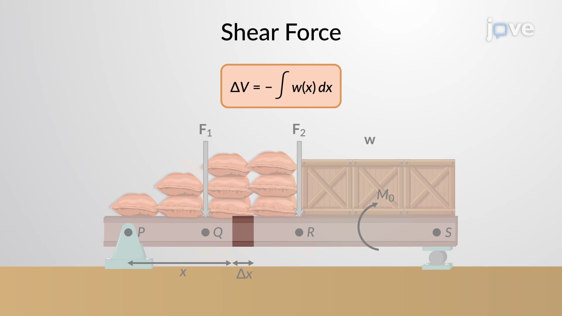
Next, the beam divides into sections between load application points. Each section receives individual analysis using equilibrium principles. Shear force calculations reveal constant values between concentrated loads but linear variations under distributed loads. This behavior reflects how loads accumulate along the beam's length.
The fundamental relationship between shear and bending moment follows a derivative relationship: the slope of the moment diagram equals the shear force value. Conversely, the area under the shear diagram between any two points equals the change in bending moment over that interval.
This mathematical relationship appears frequently in engineering coursework, including AP Physics C mechanics, university-level statics courses, and professional engineering (PE) exam problems. Students preparing for these assessments should master both the graphical construction techniques and underlying mathematical principles.
Modern applications extend beyond traditional building construction. Aerospace engineers use these concepts for aircraft wing design, automotive engineers apply them to chassis analysis, and biomedical engineers utilize similar principles for prosthetic device development. Each application requires the same fundamental understanding of how loads create internal forces and how these forces distribute throughout structural members.
Related Micro-courses