Loading video…


 14 Concepts
 24.5K views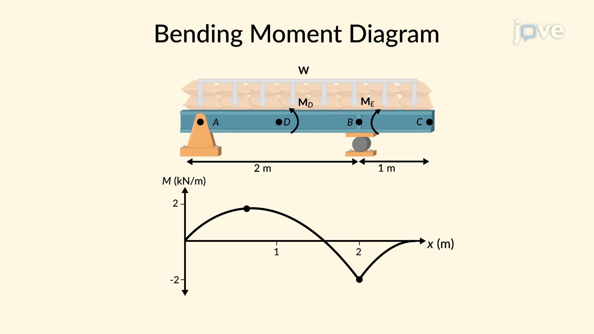

Video Summary: What Is Bending Moment Diagram
Ever wondered how engineers ensure that the Golden Gate Bridge doesn't collapse under traffic loads? A bending moment diagram is the key tool that reveals exactly where structural beams experience maximum stress. This graphical representation shows how bending moments vary along a beam's length, helping engineers design safer bridges, buildings, and aircraft structures across America. By analyzing overhanging beams under distributed loads and calculating reaction forces through equilibrium equations, students learn to construct these critical engineering diagrams. Watch the full video on JoVE Coach to master this concept with expert-led visuals and step-by-step explanations.
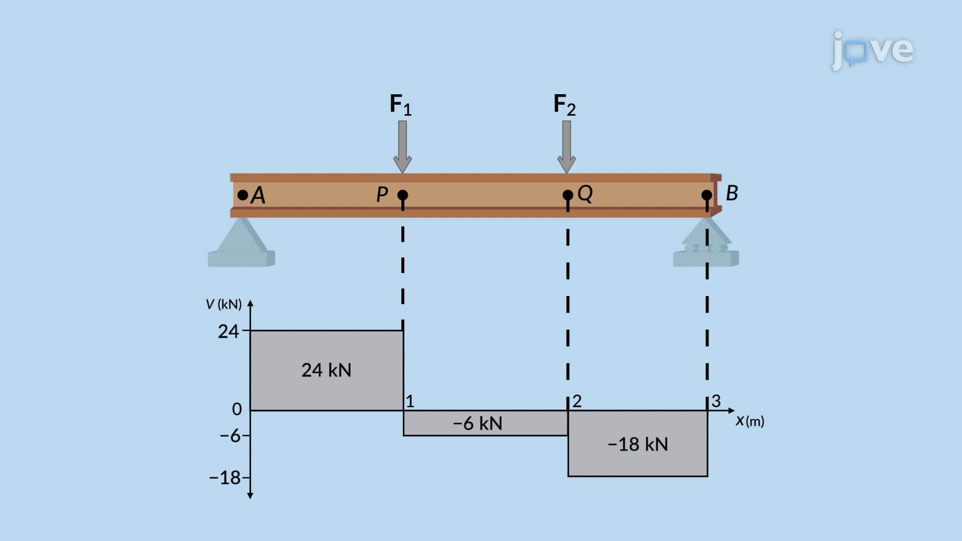
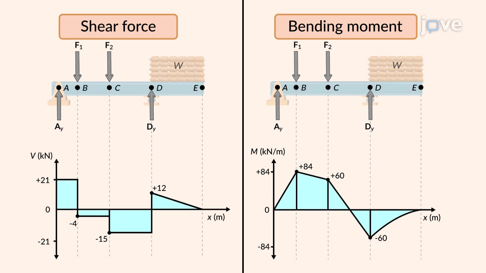
A bending moment diagram serves as the backbone of structural analysis, providing engineers with a visual roadmap of internal forces within beams. This graphical tool plots bending moments along a beam's entire length, revealing where materials experience the greatest stress and are most likely to fail. For students preparing for AP Physics or college-level statics courses, mastering this concept is essential for understanding how real structures like the supports under Interstate 95 bridges handle traffic loads safely.
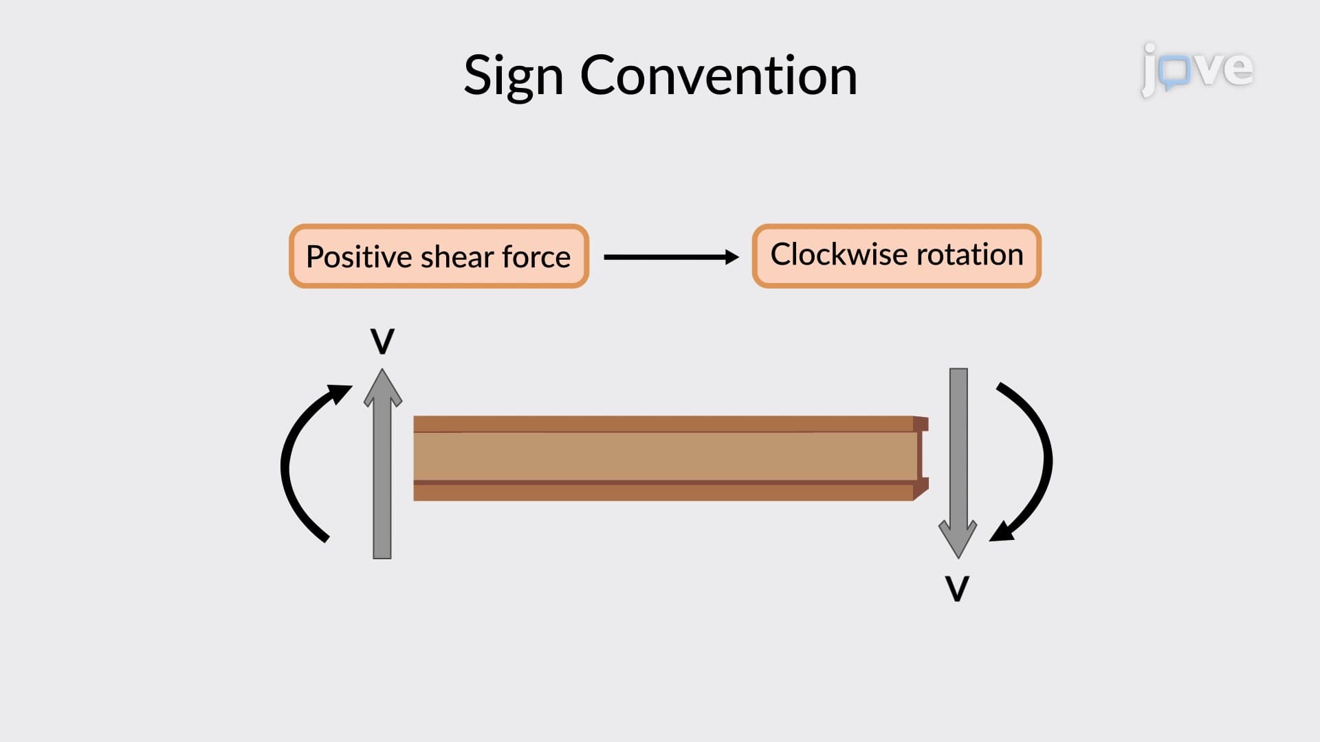
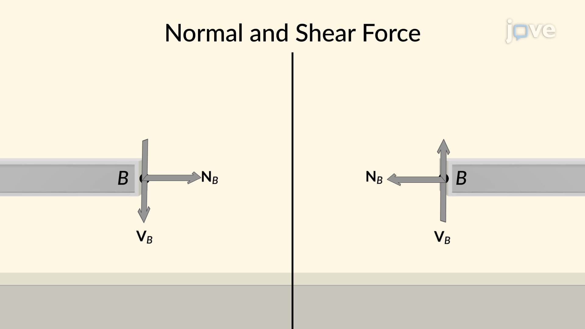
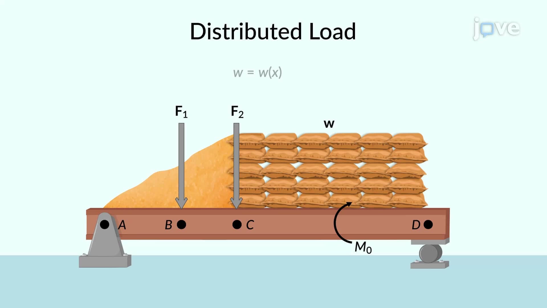
The foundation of any bending moment diagram lies in creating accurate free-body diagrams. When analyzing an overhanging beam supported at two points, engineers first isolate the structure and identify all external forces, including distributed loads, point loads, and reaction forces at supports. Using equilibrium equations (sum of forces = 0, sum of moments = 0), these unknown reaction forces become calculable values. This systematic approach appears frequently on college midterm exams and forms the basis for advanced structural engineering coursework at institutions like MIT and Stanford.
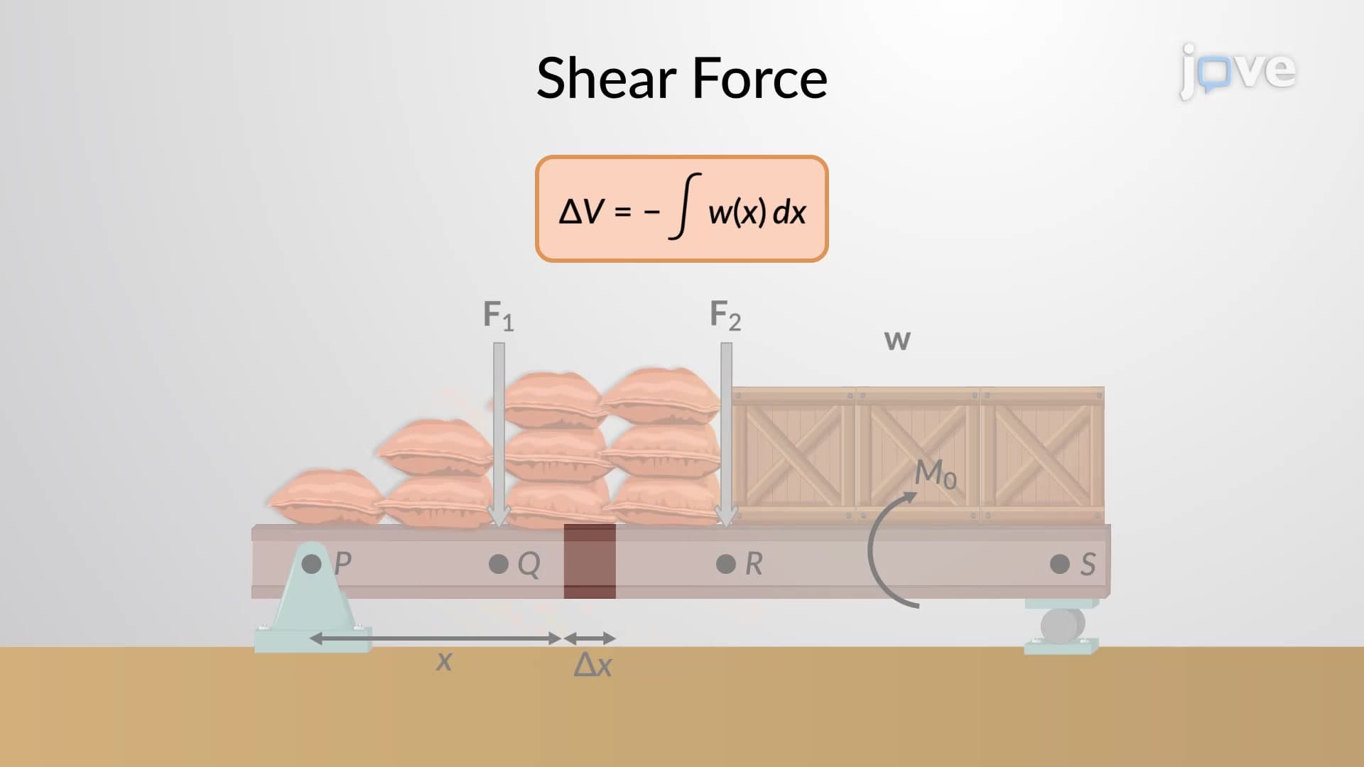
The method of sections transforms complex beam analysis into manageable mathematical problems. By "cutting" through a beam at any arbitrary distance x and analyzing the resulting free-body diagram, engineers derive moment equations for different regions. For example, in region AB of an overhanging beam, the bending moment equation might be M(x) = -wx²/2 + R₁x, where w represents distributed load intensity and R₁ is the reaction force. These equations, when plotted, create the characteristic parabolic curves seen in bending moment diagrams.
Bending moment diagrams extend far beyond textbook problems into real-world engineering challenges. When designing the structural framework for One World Trade Center in New York, engineers used these diagrams to ensure optimal beam sizing and placement. The diagrams reveal critical information: maximum positive moments indicate where tensile reinforcement is needed in concrete beams, while maximum negative moments show where compressive forces dominate. Students studying for the Fundamentals of Engineering (FE) exam will encounter these principles in structural analysis problems, making thorough understanding crucial for professional licensure.
Related Micro-courses