Loading video…


 10 Concepts
 3K views

Video Summary: Phase Lead and Phase Lag Controllers Explained
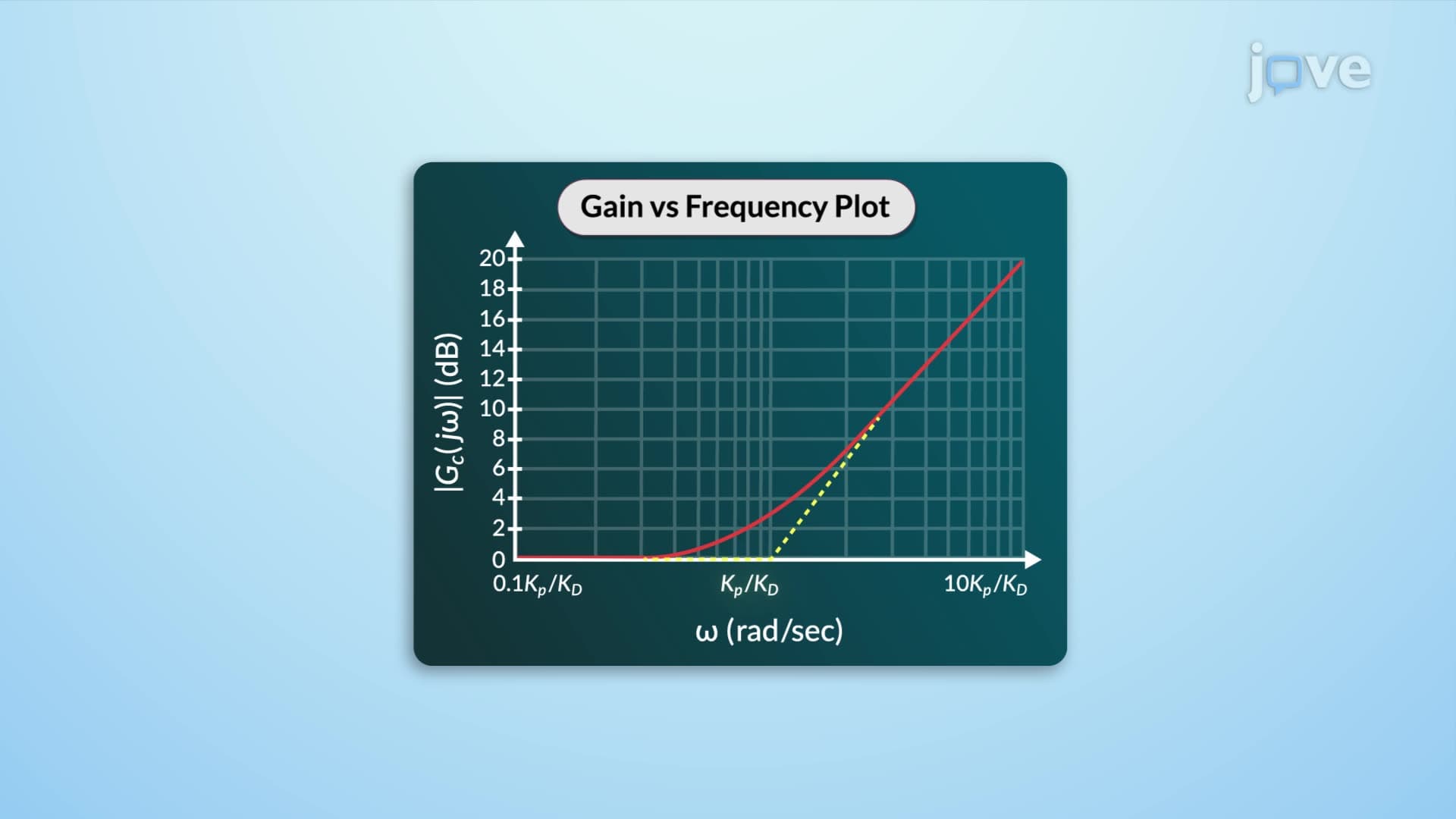
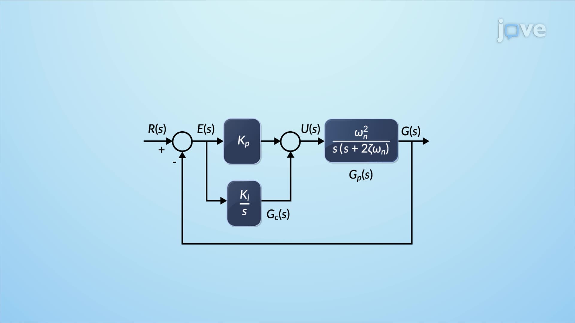
Ever wonder how noise-canceling headphones instantly adjust to block subway rumble while preserving crystal-clear phone calls? Phase lead control: time- and frequency-domain interpretation makes this possible by selectively amplifying or attenuating specific frequency ranges. Boeing's autopilot systems use these same principles to maintain stable flight paths despite turbulence. Phase Lead And Phase Lag Controllers Explained demonstrates how PD controllers function as high-pass filters while PI controllers act as low-pass filters, with PID controllers offering band-pass or band-stop capabilities. Watch the full video on JoVE Coach to master this concept with expert-led visuals and step-by-step explanations.
Phase lead control: time- and frequency-domain interpretation forms the foundation of modern control system design. These controllers manipulate system behavior by introducing strategic phase shifts across different frequency ranges. Phase lead controllers add positive phase shifts, effectively acting as high-pass filters that emphasize rapid changes and improve transient response. Conversely, phase lag controllers introduce negative phase shifts, functioning as low-pass filters that smooth out high-frequency disturbances while maintaining steady-state accuracy.
The unified transfer function G(s) = (Ts + 1)/(αTs + 1) elegantly captures both controller types. When T > αT (or α < 1), the controller exhibits phase lead behavior. When T < αT (or α > 1), phase lag characteristics emerge. This mathematical relationship directly connects to phase lead control: basics by showing how parameter selection determines filtering properties.
Students preparing for AP Physics C or college-level control systems courses should focus on this parameter relationship, as it frequently appears in exam problems requiring controller classification and design.
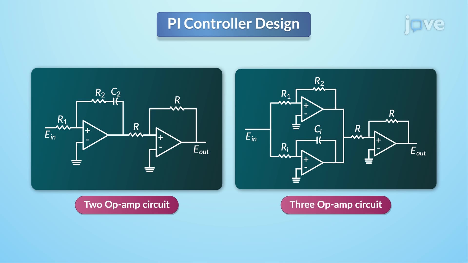
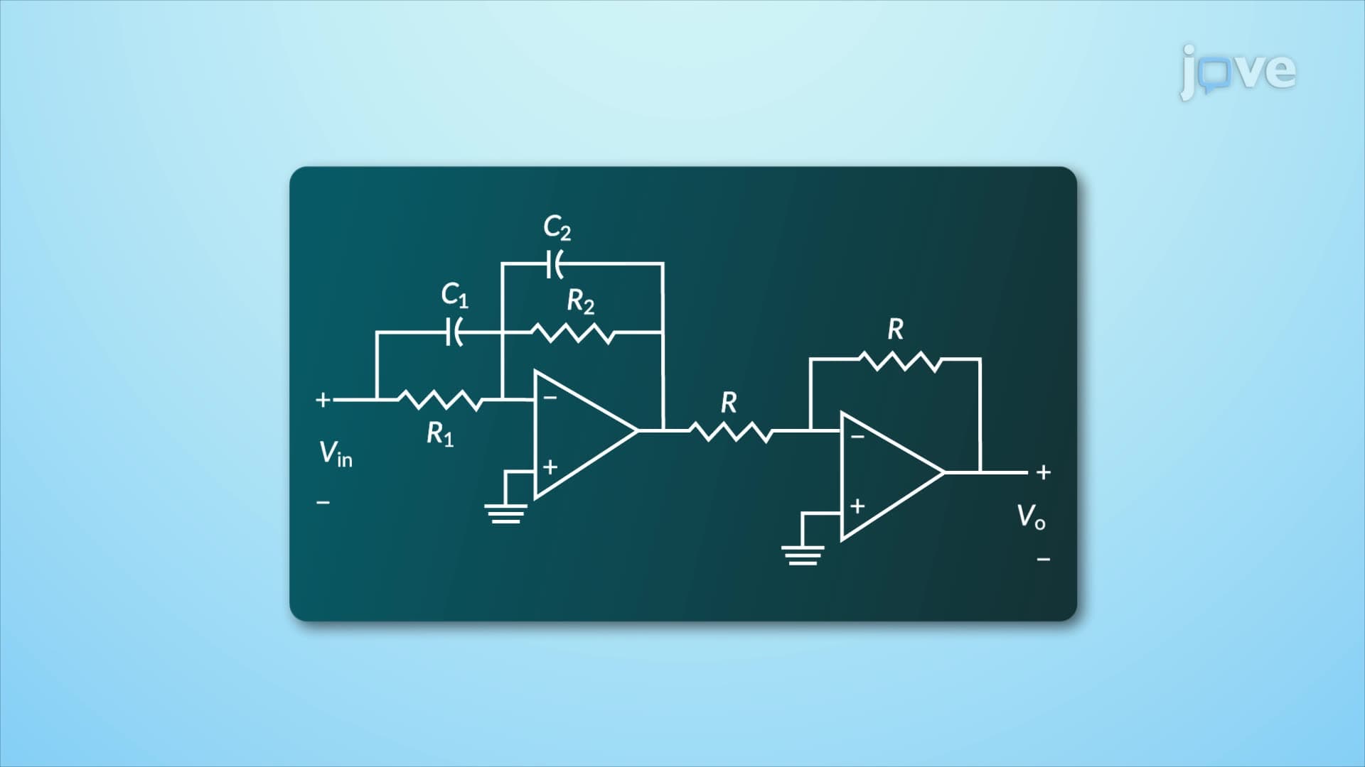
Practical implementation uses operational amplifier circuits with resistor-capacitor networks. The transfer function Vout/Vin = (R2C2s + 1)/(R1C1s + 1) demonstrates how component values determine controller behavior. By setting C1 = C2, designers reduce complexity from four parameters to three, simplifying both analysis and construction.
Understanding phase lead control: time- and frequency-domain interpretation becomes clearer when students recognize that resistance ratios (R2/R1) and time constants (RC products) directly control the frequency response shape. Texas Instruments' control system designs extensively use these principles in automotive and industrial applications.
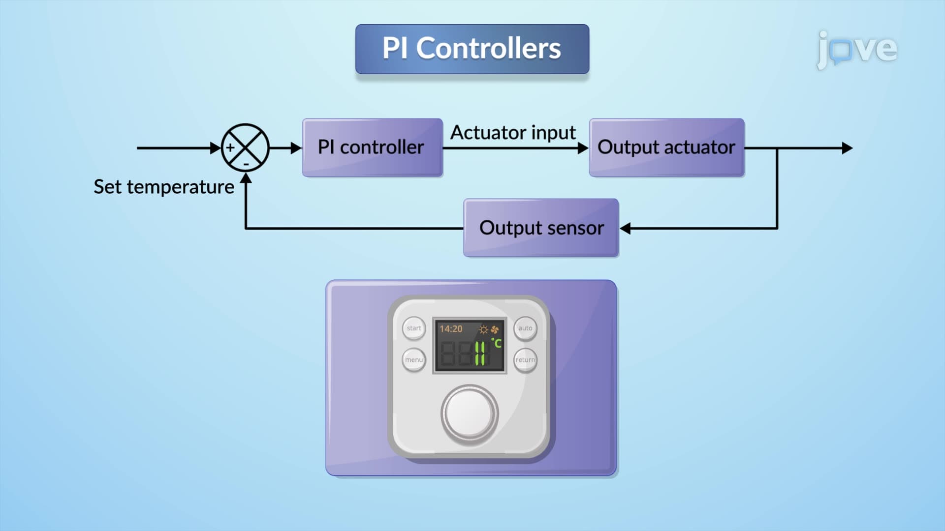
Major US manufacturers rely on these controllers daily. Ford's assembly line robots use phase lead compensation to achieve precise positioning without overshoot. Meanwhile, Honeywell's building automation systems employ phase lag controllers to maintain steady temperatures despite varying external conditions. These applications demonstrate how phase lead control: time- and frequency-domain interpretation overview translates theoretical knowledge into practical engineering solutions that students will encounter in their careers.
Related Micro-courses