Loading subject page…


11,970 views

Video Summary: What Is Minor Losses in Pipes
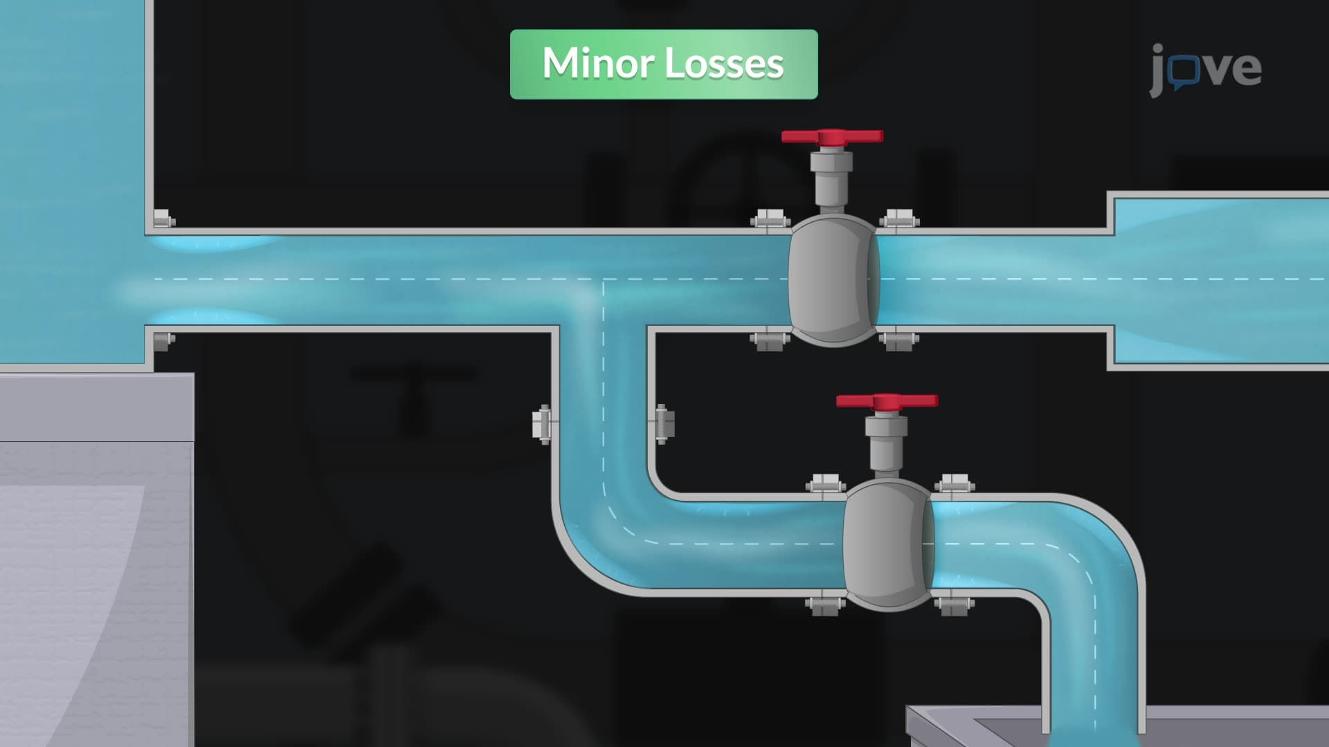
Did you know that a single elbow joint in your home's plumbing can cause more energy loss than 20 feet of straight pipe? In single pipe systems, components like valves and bends create what engineers call "minor losses" - energy dissipation that occurs when fluid flow is disrupted. Consider the Chicago water distribution system, where thousands of fittings collectively impact pressure throughout the network. Watch the full video on JoVE Coach to master this concept with expert-led visuals and step-by-step explanations.
Minor losses in pipes represent a critical concept in fluid mechanics that extends far beyond the friction losses found in straight pipe sections. While the term "minor" might suggest these losses are insignificant, they often constitute the dominant source of energy dissipation in real piping systems. In single pipe systems, these losses become particularly important because they can dramatically affect system performance and efficiency.
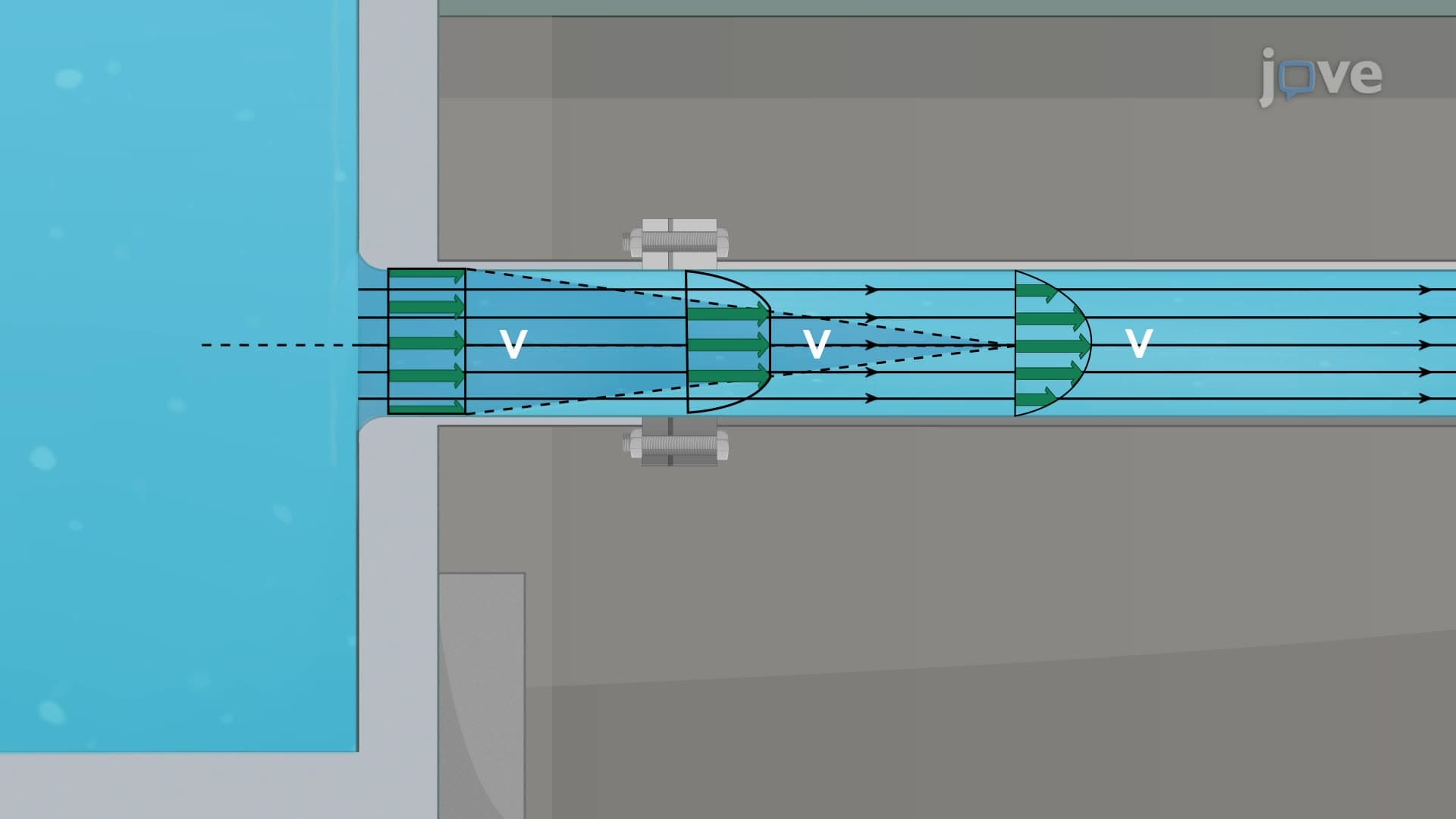
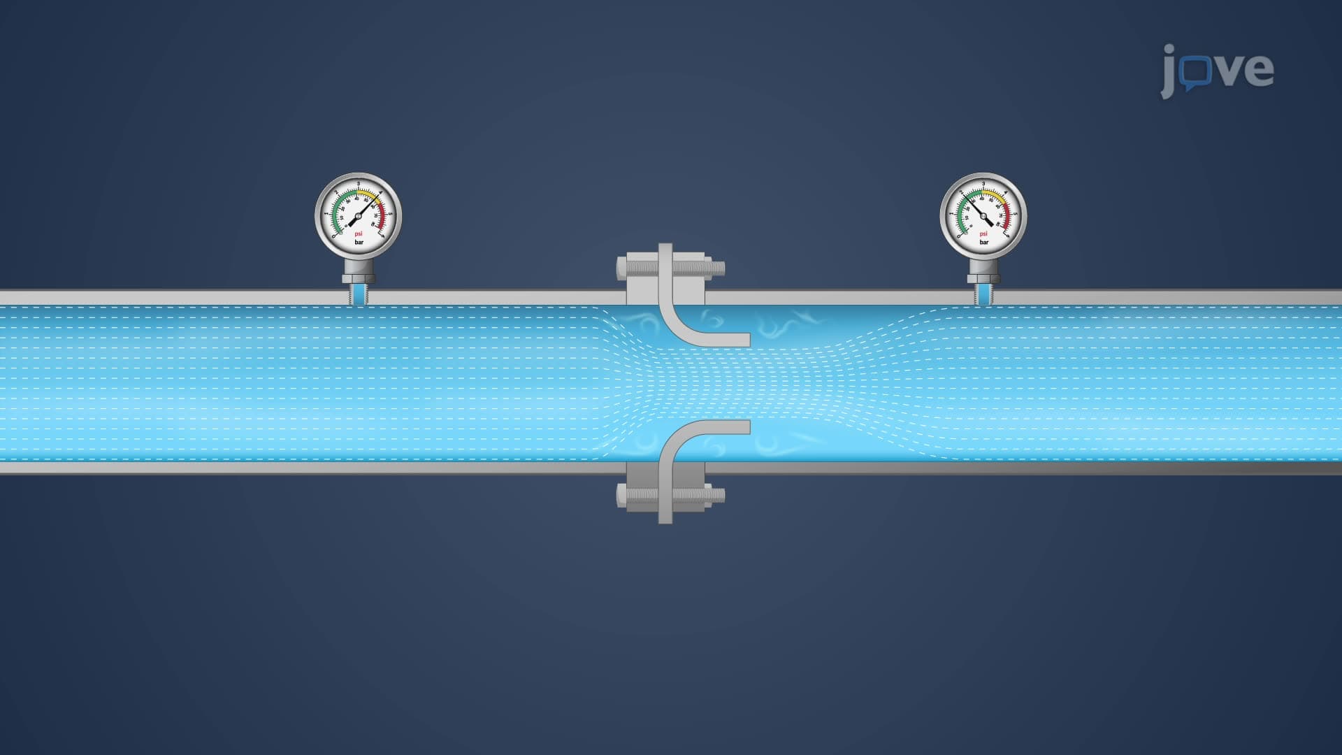
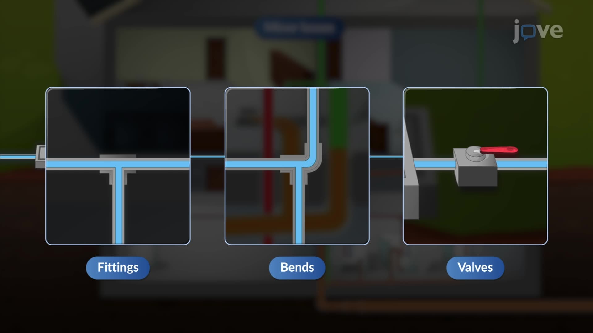
The primary culprits behind minor losses include valves, elbows, tees, reducers, and other fittings that interrupt the smooth flow of fluid. When water flows through a gate valve in a municipal water system, for example, the valve creates a constriction that accelerates the fluid, followed by expansion that generates turbulence and energy loss. This phenomenon is quantified using dimensionless loss coefficients (K) that depend on the specific geometry of each component.
The mathematical relationship follows the pattern: head loss = K × (velocity squared)/(2×gravity). This square relationship with velocity means that doubling the flow rate quadruples the minor losses - a critical consideration in system design. For AP Physics or college fluid mechanics courses, students often encounter problems requiring calculation of total system head using both major and minor loss components.
Engineers frequently use the equivalent length method to simplify complex calculations involving types of single pipe systems. This approach converts each fitting into an equivalent length of straight pipe that would produce the same head loss. For instance, a standard 90-degree elbow might have an equivalent length of 30 pipe diameters, meaning it creates the same energy loss as 30 diameters of straight pipe.
This method proves invaluable when designing systems like those found in pharmaceutical manufacturing facilities or chemical processing plants, where precise pressure calculations are essential for product quality and safety. Understanding single pipe systems overview becomes crucial for engineering students who will later design everything from building HVAC systems to industrial process piping.
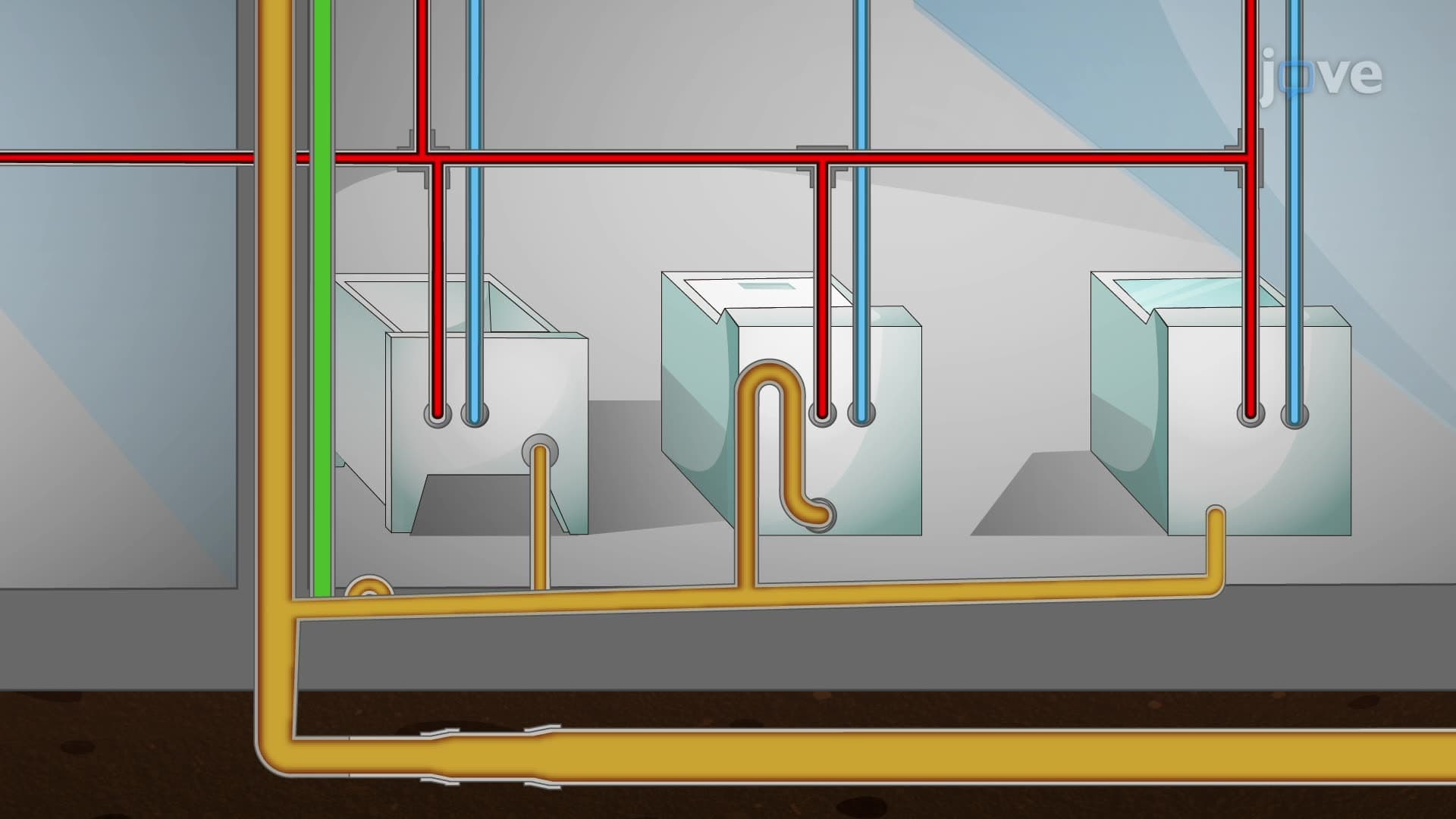
In practice, minor losses often dominate system behavior. Consider a typical residential plumbing system where the equivalent length from fittings may exceed the actual pipe length by a factor of two or three. The entrance loss at a pipe inlet, the various elbow and tee fittings throughout the system, and the exit loss all contribute significantly to the total pressure drop.
For students preparing for engineering exams or professional practice, mastering single pipe systems basics provides the foundation for more complex network analysis and pump selection procedures used throughout the industry.
Related Micro-courses