21 Concepts
14 Concepts
11 Concepts
11 Concepts
16 Concepts
8 Concepts
18 Concepts
12 Concepts
6 Concepts
12 Concepts
6 Concepts
5 Concepts
6 Concepts
9 Concepts
8 Concepts
8 Concepts
7 Concepts
9 Concepts
10 Concepts
8 Concepts
13 Concepts
5 Concepts
11 Concepts
10 Concepts
7 Concepts
6 Concepts
9 Concepts
10 Concepts
6 Concepts
9 Concepts
Flow in pipes is fundamental to understanding how fluids move through enclosed systems under pressure-driven conditions. This comprehensive course covers laminar and turbulent flow regimes, energy losses, and practical pipe system design. Students explore Reynolds number calculations, the Darcy-Weisbach equation, and real-world applications from municipal water systems to residential plumbing networks across the United States.
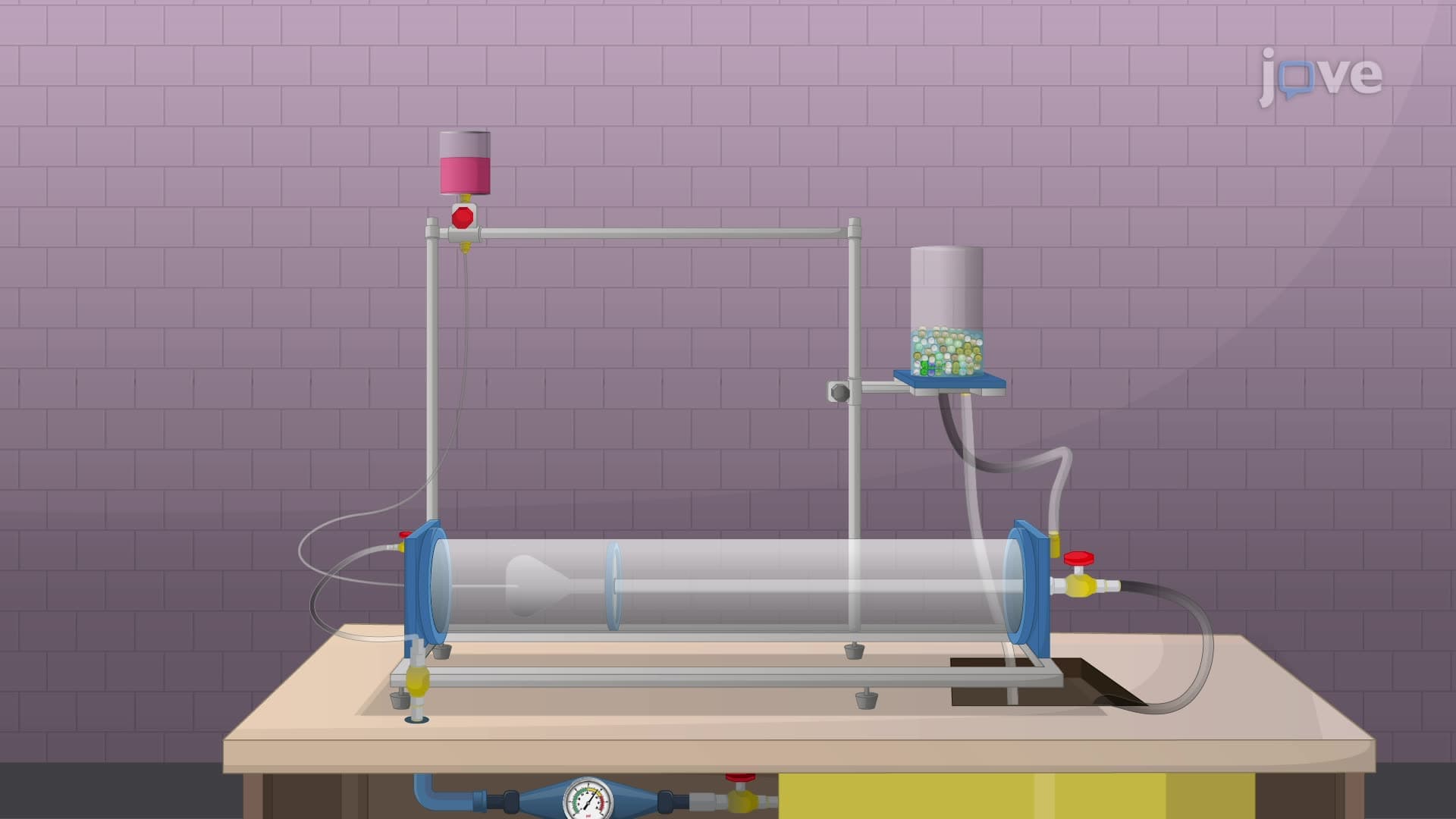
1. Reynolds Number and Flow Classification The Reynolds number determines whether flow in pipes will be laminar (smooth, orderly) or turbulent (chaotic, mixing). For circular pipes, flows are typically laminar below Re = 2,100 and turbulent above Re = 4,000. This dimensionless parameter depends on fluid velocity, density, viscosity, and pipe diameter. Understanding flow classification is crucial for predicting pressure drops in systems like the water distribution network serving New York City, where different flow regimes occur simultaneously across the massive pipe network spanning over 6,000 miles.
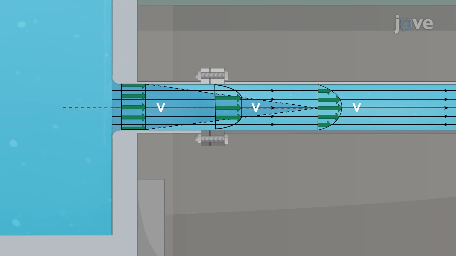
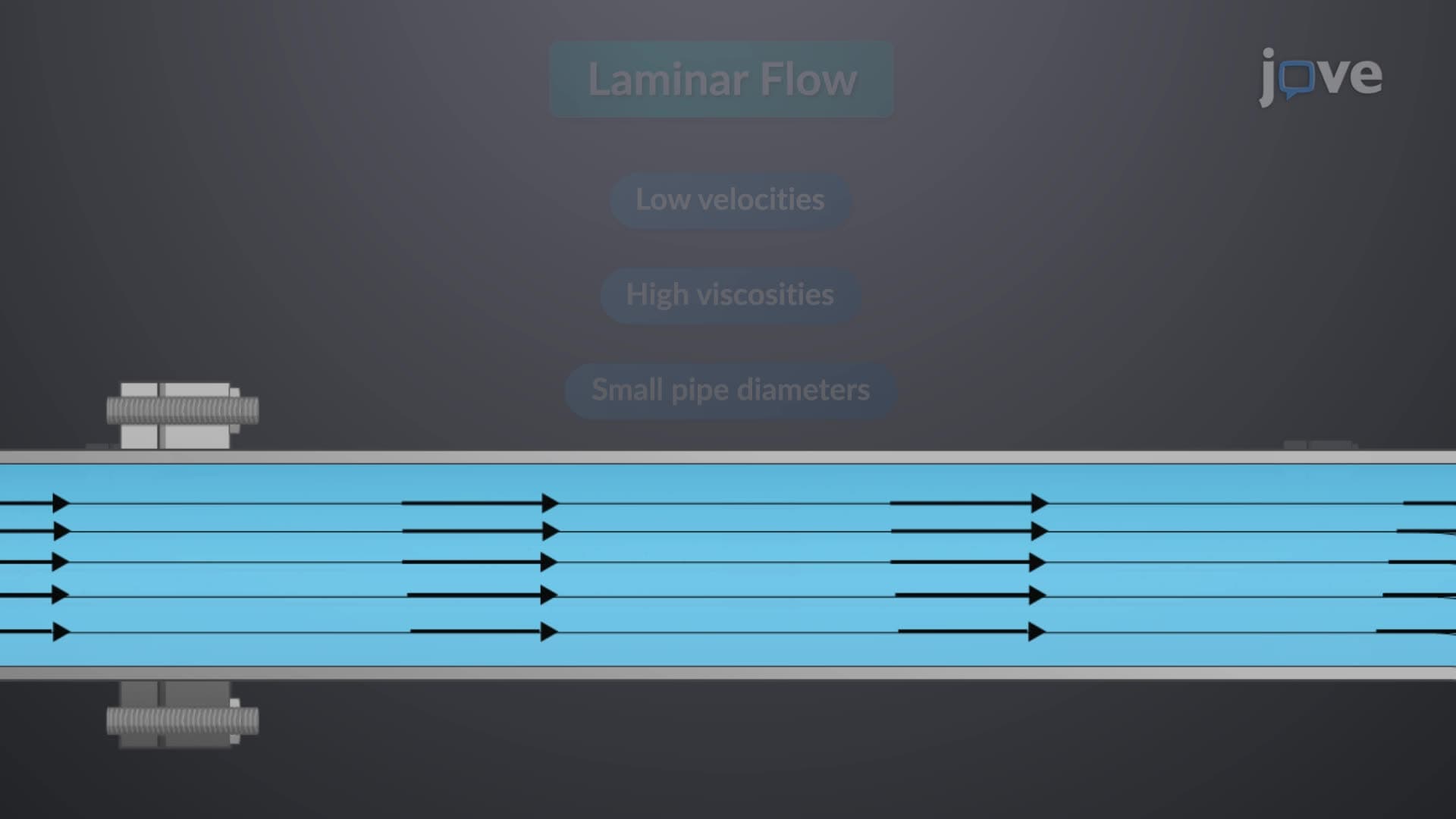
2. Laminar Flow Characteristics and Applications Laminar flow features smooth, parallel fluid layers with minimal mixing between them. The velocity profile develops into a parabolic shape over the entrance length, governed by the Hagen-Poiseuille equation. This flow type minimizes energy losses and is essential in applications requiring precise control, such as pharmaceutical manufacturing facilities in Research Triangle Park, North Carolina, where contamination prevention is critical. Laminar conditions also occur in small-diameter pipes carrying viscous fluids like heating oil in residential systems throughout colder US states.
3. Turbulent Flow and Energy Dissipation Turbulent flow exhibits chaotic pressure and velocity fluctuations with enhanced mixing characteristics. The flow structure includes three distinct zones: the viscous sublayer near pipe walls, the buffer layer with logarithmic velocity distribution, and the outer turbulent region dominated by random eddies. This flow type is common in municipal water systems serving cities like Los Angeles, where high velocities in large-diameter pipes ensure efficient transport but require careful energy management to minimize pumping costs across the extensive distribution network.
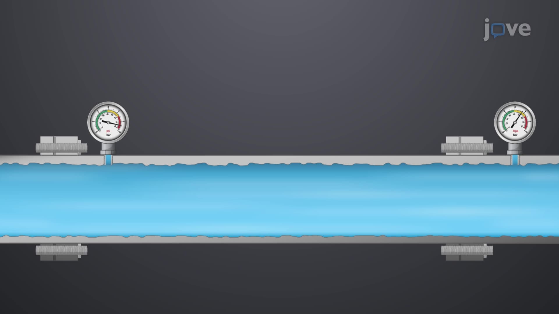
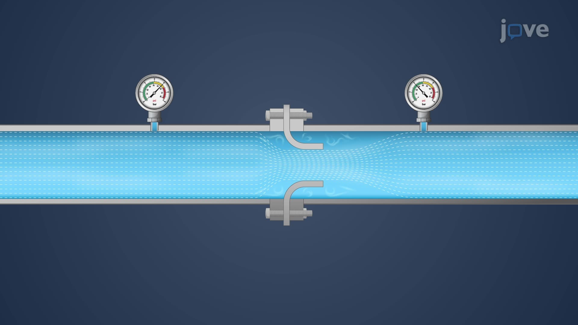
4. Major Losses and the Darcy-Weisbach Equation Major losses represent energy dissipation due to friction along straight pipe sections, calculated using the Darcy-Weisbach equation: hf = f(L/D)(V²/2g). The friction factor f depends on Reynolds number and relative pipe roughness, determined from the Moody chart. These calculations are essential for designing systems like the Colorado River Aqueduct, where water travels over 240 miles through large pipes to supply Southern California. Engineers must accurately predict these losses to size pumping stations and maintain adequate pressure throughout the system.
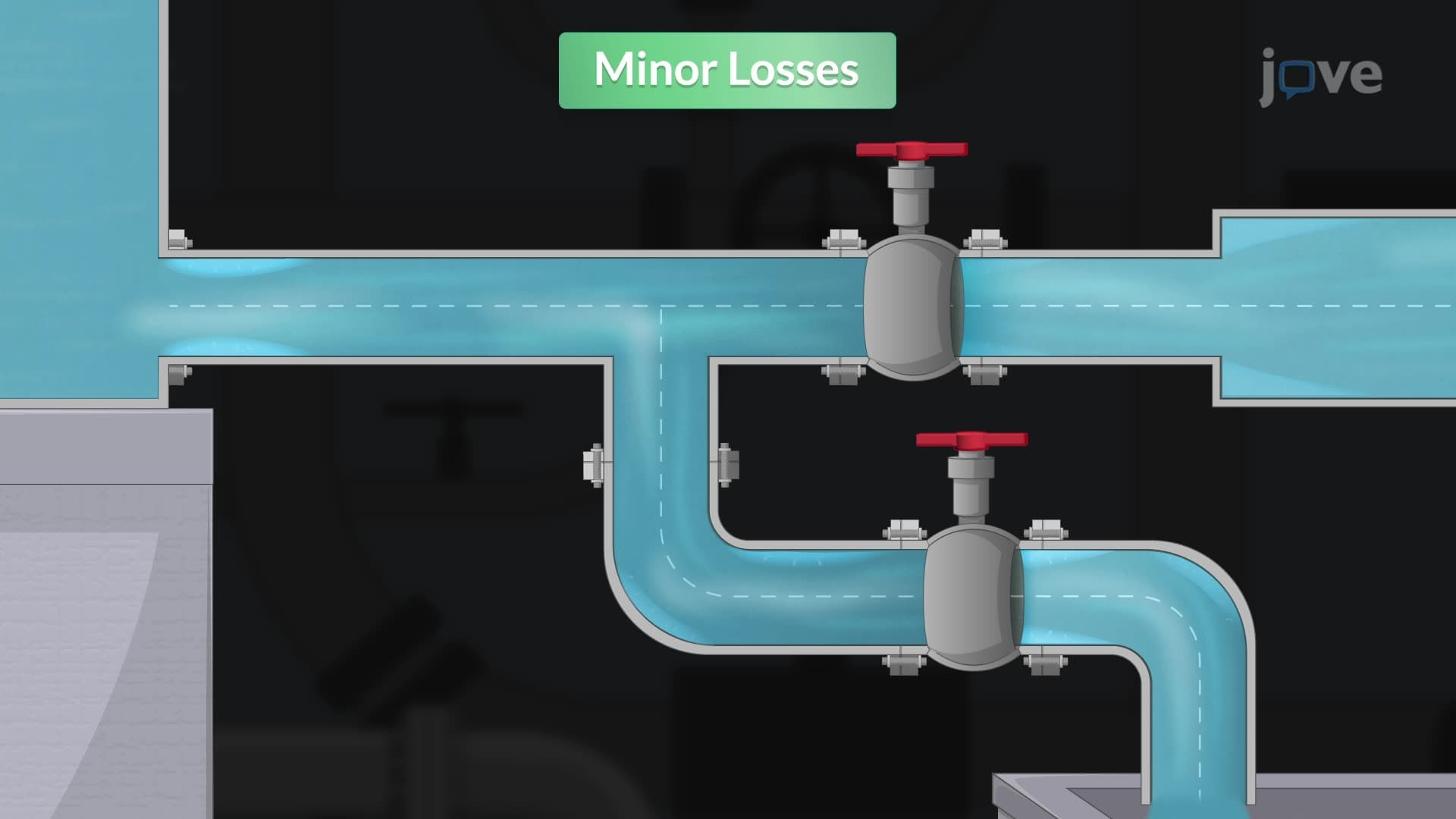
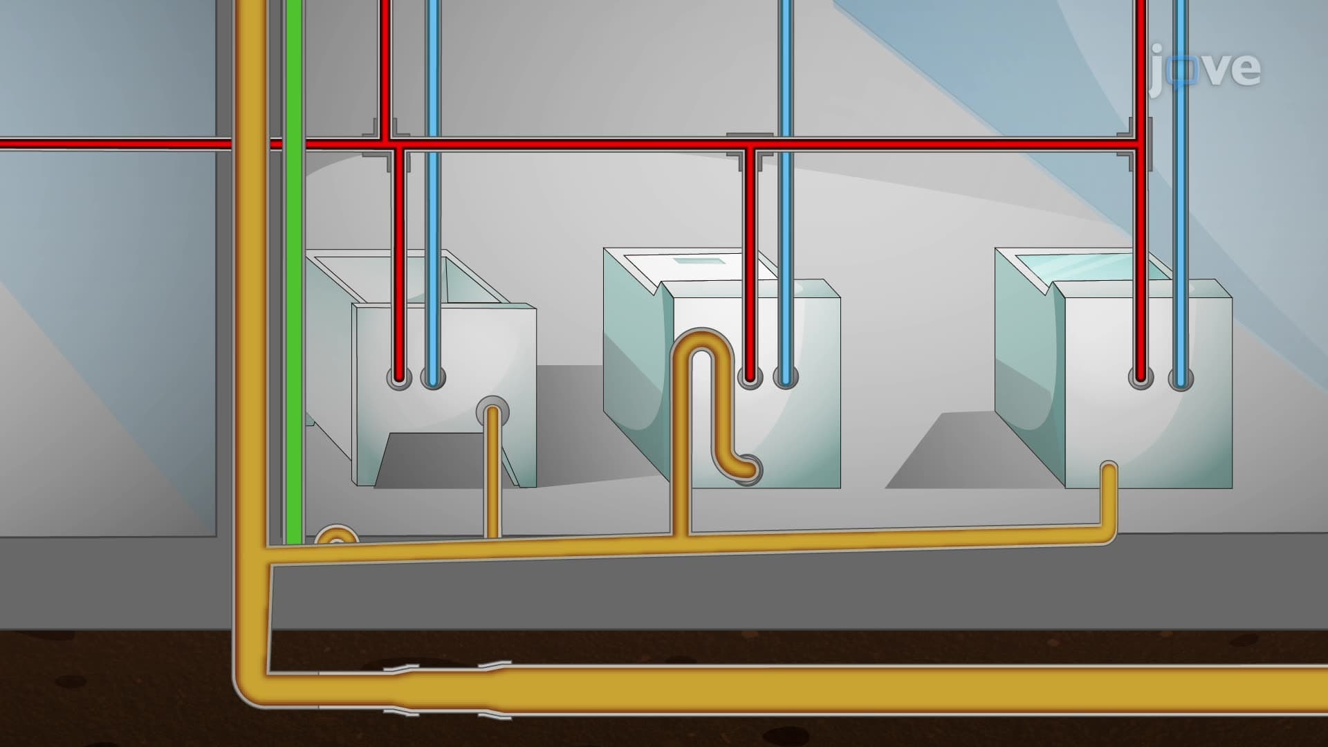
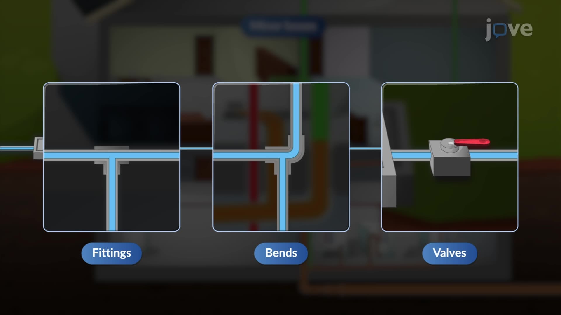
5. Minor Losses from Fittings and Components Minor losses occur at pipe fittings, valves, bends, and area changes, causing flow disruption and energy dissipation. These losses are quantified using loss coefficients (K) in the equation hL = K(V²/2g), or expressed as equivalent lengths of straight pipe. In residential plumbing systems across American suburbs, minor losses from elbows, tees, and fixtures can significantly impact overall system performance, especially in multi-story buildings where multiple fittings create cumulative pressure drops affecting upper-floor water delivery.
6. Multiple Pipe System Analysis Complex pipe networks include series, parallel, loop, and branching configurations common in municipal infrastructure. Series systems maintain constant flow rate with additive head losses, while parallel systems split flow with equal head losses across all branches. Loop systems require continuity and energy balance at junction points. These principles govern the design of water distribution systems serving major metropolitan areas like Chicago, where interconnected pipe networks ensure reliable supply even when individual sections require maintenance or experience failures.
7. Flow Measurement and Instrumentation Flow measurement devices including orifice plates, nozzles, and Venturi meters operate on Bernoulli's principle, creating pressure differentials proportional to flow rates. Each device has specific discharge coefficients accounting for real-world effects like flow contraction and viscous losses. These instruments are essential in industrial applications throughout the US chemical industry, particularly in refineries along the Gulf Coast, where accurate flow measurement ensures process control, environmental compliance, and safety in handling various fluid streams with different properties and hazard classifications.